Anyways, I'm convinced I'm better off buying a better DAC, I have just one other query first.
An ES9018 board is 8ukp, an ES9038 board is 38ukp, is there enough of a difference between those two chips to justify the extra expense, given I'm on a tight budget?
Given how cheap the ES9018 boards are, what about using two of them in mono mode?
An ES9018 board is 8ukp, an ES9038 board is 38ukp, is there enough of a difference between those two chips to justify the extra expense, given I'm on a tight budget?
Given how cheap the ES9018 boards are, what about using two of them in mono mode?
There have been a lot of improvements since ES9018. ASRC jitter reduction sounds better. With 9018 people often said it sounded better with ASRC off which is a problem in many cases. It means jitter has to managed in another way. Best to go with ES9038 which has
a number other useful new features in addition to improved ASRC.
In addition, over time as and you can you will probably be investing some additional money and some work into whatever you dac you choose. May as well choose something you will be happy with for a long time. The first mods only require some opamps, resistors, and caps, but somehow you will need an adequate +-15v power supply. Linear is by far the best choice for that, but it can be an LM317/LM337 type supply. Also, two or three small 3.3v 8-pin dip regulators on the dac board should be useful. Those things are mostly pretty low cost. Later a new clock is a moderate expense at around $30. At good headphone amp and mods for it which you should do at some point to really hear what your dac can do might cost around $30 - $40. The most expensive single mod would be a good sample rate converter board with Amanero or XMOS USB to PCM/DSD board. That combo can cost from around $90 - $130 or even $180. But, once you get everything else done that last step is well worth it. It gets you up into $1,000+ class sound quality. Along the way you can always stop and start as you like, or you can decide to stop for good. If you keep going you might well end up with a dac that will be highly satisfactory for a decade or more, maybe the envy of your friends for that long too.
Last edited:
(snip)
Well, almost pointless, the point of buying the very cheap Cirrus USB DAC was to give me some practice and experience before moving on to using more expensive components.
Hi Andersonix, how are you finding the direct output solution with the DAC output into a pair of hefty caps? Is it sounding good or have you changed things since?
My Oppo DVDP with CS4361 running 'direct out' is sounding very good, encouraging me to try it again in another one with some higher regarded 3.3uF Clarity caps and an easier way to swap caps. What do you mean by "hefty"?
You owe it to your listening experience to hear your DAC in its simplest configuration, as this way you're basically (layout permitting) hearing the 5V supply through the caps you've chosen. KISS sounds best.
Thanks Mark, that is extremely helpful.
So I'm convinced now that the ES9038 is the one to go with, not just because it's a more capable piece of kit, but also, there is a body of prior knowledge and experience to guide me.
I've been looking at high end DACs, especially pictures of their innards and it seems to me that they almost all follow the same overall design philosophy:
Separate digital and analogue sections
Separate PSUs for the digital and analogue sections
So in my way of thinking, it breaks down into four basic parts:
Digital section - inputs, DAC
PSU for digital section
Analogue section - usually incorporating valves/tubes, but sometimes solid state
PSU for analogue section - in most designs, this is 2-3x larger with 2-3x more capacitors than the digital PSU
So if I buy an ES9038, that's the digital section, and the PSU from the Cambridge D100 should suffice to power that. A second PSU and an analogue section can be obtained later, I'll worry about the DAC and a PSU for it first.
Any obvious flaws in my thinking?
My Oppo DVDP with CS4361 running 'direct out' is sounding very good, encouraging me to try it again in another one with some higher regarded 3.3uF Clarity caps and an easier way to swap caps. What do you mean by "hefty"?
You owe it to your listening experience to hear your DAC in its simplest configuration, as this way you're basically (layout permitting) hearing the 5V supply through the caps you've chosen. KISS sounds best.
Cheers, useful info.
Hefty is an English word meaning large, beefy, strong, you would describe an NFL linebacker or a sumo wrestler as 'hefty'.
That's a good point about listening to the raw DAC output, I can do that at the beginning, before building and adding an analogue stage, seeing as it just requires a couple of 'hefty' caps, it's not going to be costly. It might sound nice enough to my ears that I can take my time about an analogue section, or perhaps even omit one altogether.
You only need +-15 volt supplies to start with. The dac boards have 5v and 3.3v regulators that run from the +15v supply. You would need a small 8-pin 3.3 regulator for AVCC, and maybe another for VCCA and the clock. Those get power from the 5v regulator. If you want to know more you should come over to the other thread and we can talk about options to proceed from there. That way other people who may be interested in getting started with an ES9038Q2M can read along and or ask questions too.
I bought one of these, now just got to wait for it to arrive on the boat from China:
Assembled ES9038 DAC board Q2M I2S DSD 256K Optical Coaxial Input Decoder | eBay
Assembled ES9038 DAC board Q2M I2S DSD 256K Optical Coaxial Input Decoder | eBay
You only need +-15 volt supplies to start with. The dac boards have 5v and 3.3v regulators that run from the +15v supply. You would need a small 8-pin 3.3 regulator for AVCC, and maybe another for VCCA and the clock. Those get power from the 5v regulator. If you want to know more you should come over to the other thread and we can talk about options to proceed from there. That way other people who may be interested in getting started with an ES9038Q2M can read along and or ask questions too.
I'm going to see what parts of the Cambridge D100's PSU I can re-use, certainly the nice shielded toroidal transformer, there is also a small PCB connected to that, which I might be able to use too, not sure what that does in terms of regulation and conversion, when the D100 arrives I can tear it down and make photos of everything so we can figure it out.
Do you mean this thread?
ES9038Q2M Board
When I start building this thing I guess I should start a new thread to cover the build.
...before building and adding an analogue stage, seeing as it just requires a couple of 'hefty' caps, it's not going to be costly. It might sound nice enough to my ears that I can take my time about an analogue section, or perhaps even omit one altogether.
Looks like the dac chip you currently have is designed for use with a passive output network. That would make sense if the dac is intended to be a simple, low-cost solution that can be easily integrated into other products. It doesn't take or need state of the art opamps to use, and it wouldn't make sense if it did. Things like that add cost and complexity when in reality most consumer devices are built to a price-point to fit into a particular market segment.
OTOH, when we talk about dacs that cost almost $1k/channel with state of the art specifications and sound quality, then it is probably reasonable to expect that one single chip is not going to be able to do it all.
As an aside, there was another thread around here somewhere with the idea that 'the best dac is no dac.' IIRC, it was an effort to make a passive DSD player network. Mostly it was just a low pass filter. Again, IIRC, it kind of worked but wasn't the best sounding DSD solution around.
BTW, the ES9038Q2M can play PCM up to 960kHz, DoP and native DSD512. You will be able to play whatever formats you like.
It is indeed their heft which limits which film caps I can use, or the cover may not fit.
That's a good point, I just measured by Cambridge Azur 340C and the case is 2 3/4 inches tall, I expect the D100 I've bought to use as a case for my project is the same or slightly smaller, so that places a physical limit on the size of caps and transformer I could cram in there.
Yes, that is the thread I provided links to in a previous post here so you could see pictures of a modded dac board and a modded headphone amp board. I still would suggest you look at those pictures to see what kinds of things were involved in at least one way of laying out some circuitry. The top and bottom of the board were both modified. If you compare those pictures to the picture of the new board I linked to that you might consider buying, you can see quite a bit was changed. There are other ways to lay it it out that are less demanding, but there are some good considerations for doing it the way I did. I would of course be happy to point to some other useful references whenever it would be of interest to dig in a little deeper. Please let me know anytime if you would like more reading material, there is a lot to study
")
Last edited:
Well, now I have the ES9038 ordered, and an enclosure and PSU in the form of the Cambrdige D100, I can at least put together something that works, so I'll to get past that hurdle first, then we can worry about an analogue stage, be it a pair opf capacitors or something altogether more complex.
Much appreciate all the advice, I shall start a new thread to cover the build once I have some of the parts in hand.
Much appreciate all the advice, I shall start a new thread to cover the build once I have some of the parts in hand.
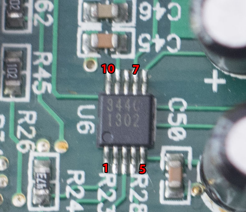
There is a data sheet here: http://www.mouser.com/ds/2/76/CS4344-45-48_F2-472818.pdf
It shows what the pins are and their electrical properties. Page 11 of the data sheet shows how to hook up the outputs.
It shows what the pins are and their electrical properties. Page 11 of the data sheet shows how to hook up the outputs.
Cheers, according to that datasheet The output pins are 7 and 10.
Just to make sure I'm not confused, I made this annotation to check:
I traced the tracks on the board and it turns out they lead to the volume pot:

Long traces like that before going into a couple of caps then into the pot doesn't look like good practice to me, but what the hell, this is a cheap thing so be it.
Looks like the best place to solder on the wires is the pins of those two caps, there is no chance of me being able to solder wires to the teeny pins of the DAC chip itself.
Just to make sure I'm not confused, I made this annotation to check:
I traced the tracks on the board and it turns out they lead to the volume pot:
Long traces like that before going into a couple of caps then into the pot doesn't look like good practice to me, but what the hell, this is a cheap thing so be it.
Looks like the best place to solder on the wires is the pins of those two caps, there is no chance of me being able to solder wires to the teeny pins of the DAC chip itself.
Attachments
Last edited:
The other thing I need to figure out and am confused by is how the power input to this thing works. It only has a USB connection, no other way to connect power to it, so it takes the power from the USB.
There is what looks like a very small voltage reg on the board, and solder pads for a much larger regulator, with a cap placed both before and after the small reg.
I'd like to connect a 5v supply to this thing, other than via USB, the question is where to connect to?

There is what looks like a very small voltage reg on the board, and solder pads for a much larger regulator, with a cap placed both before and after the small reg.
I'd like to connect a 5v supply to this thing, other than via USB, the question is where to connect to?
Attachments
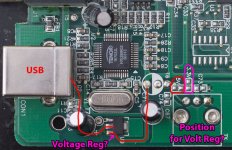
Are there any markings you can identify on U9? I would guess it'd be an AMS1117 3.3V reg but the way you've drawn the red lines doesn't agree with its pinout.
Incidentally what you've labelled as a potential voltage reg is probably just a Toslink connector. The give-away is the two letters 'TX' on the silkscreen (bottom right) - its a Toslink transmitter for S/PDIF output as an option.
Incidentally what you've labelled as a potential voltage reg is probably just a Toslink connector. The give-away is the two letters 'TX' on the silkscreen (bottom right) - its a Toslink transmitter for S/PDIF output as an option.
Last edited:
- Status
- This old topic is closed. If you want to reopen this topic, contact a moderator using the "Report Post" button.
- Home
- Source & Line
- Digital Line Level
- Upgrading cheap Cirrus Logic CS4344 24-bit, 192 kHz Stereo DAC