The impulse response is sometimes useful but very difficult to use correctly in a digital system because it is bandlimited one. Pre and post ringing of a digital filter is one of them. IMHO, the impulse response of a digital filter gives you many misunderstandings and less information. It's better not to use it for that purpose. If you have two digital filters which have the same frequency response, but the impulse response of them are usually not same. It depends on sampling frequency. So, impulse response without referring sampling frequency is theoretically meaningless for an engineer.
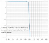
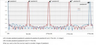
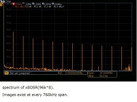
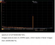
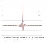
For example, the 1st pic is ordinary brick wall filter which can be implemented by several sampling frequencies(x1,x4, and x16OSR). Many people don't know one important thing a digital filter is a periodic function in frequency domain. The 2nd pic shows how a digital filter works. It has image passband. x1OSR has more images than x4OSR. Even if the first passband is same between x1OSR and x4OSR, the impulse response what you see is not same because the infinite spectrum of the impulse ends up another result. The 3rd and 4th pic are a real spectrum of x8OSR and x64OSR.
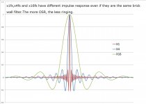
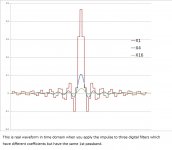
The 5th pic shows the impulse responses of x1OSR,x4OSR, and x16OSR. They have the same 1st passband which is usually the target but have different images. That's why their impulse responses are different. But I'm at a loss how to explain the 6th pic which is real coefficients of the digital filters. The impulse response is theoretically equal to the coefficients. I can't answer which is better to analyze a digital filter(both sampling frequency and amplitude are mandatory ?). My conclusion is that you don't need to worry about the impulse response because there is another way to analyze a digital filter.")
For example, the 1st pic is ordinary brick wall filter which can be implemented by several sampling frequencies(x1,x4, and x16OSR). Many people don't know one important thing a digital filter is a periodic function in frequency domain. The 2nd pic shows how a digital filter works. It has image passband. x1OSR has more images than x4OSR. Even if the first passband is same between x1OSR and x4OSR, the impulse response what you see is not same because the infinite spectrum of the impulse ends up another result. The 3rd and 4th pic are a real spectrum of x8OSR and x64OSR.
The 5th pic shows the impulse responses of x1OSR,x4OSR, and x16OSR. They have the same 1st passband which is usually the target but have different images. That's why their impulse responses are different. But I'm at a loss how to explain the 6th pic which is real coefficients of the digital filters. The impulse response is theoretically equal to the coefficients. I can't answer which is better to analyze a digital filter(both sampling frequency and amplitude are mandatory ?). My conclusion is that you don't need to worry about the impulse response because there is another way to analyze a digital filter.
Attachments
- Status
- This old topic is closed. If you want to reopen this topic, contact a moderator using the "Report Post" button.