I would like to take (if possible) the line level from a tablet or amazon DOT, and send one channel to a woofer (8 ohms) and the other channel to a 4 ohm full range. The amp is a tpa3100d2, which according to the data sheet has an input impedance of 13 to 36 ohms depending on how the gain is set. Can someone point me to a site or help out with the components needed for:
Xover 150 and a different one at 75
Woofer Low pass cap = Inductor =
Full range high pass cap = inductor = .
What are your opinions on using a RC filter (resistors vs inductors)
I would be willing to accept a little less audio quality just to test.
Thanks
Xover 150 and a different one at 75
Woofer Low pass cap = Inductor =
Full range high pass cap = inductor = .
What are your opinions on using a RC filter (resistors vs inductors)
I would be willing to accept a little less audio quality just to test.
Thanks
It seems you overlooked a factor of 1000; the amplifier's input resistance is 12.8 kohm to 38.4 kohm according to the datasheet.
Are you looking for an active filter between source and amplifier, for a passive filter between amplifier and loudspeaker, or considering both?
Assuming a passive filter:
Quality factor of a second-order Linkwitz-Riley filter: 0.5 by definition
Quality factor of a second-order low-pass with 0 source resistance and load Rload:
Q = Rload/sqrt(L/C)
Cut-off: fn = 1/(2 pi sqrt(LC))
Hence,
L = (Rload/Q) / (2 pi fn)
C = 1/(4 pi^2 fn^2 L)
It's 4:10 AM here at the moment, so maybe it's a good idea to wait with ordering the components until someone who is fully awake has checked these equations.
By the way, shouldn't this be in the multiway loudspeaker forum?
Last edited:
Thanks for responding marcelvdg - I'm looking for the filters between the source and the amp, not between the amp and speaker as I think, maybe wrongly, that the values will be less, not as expensive and the sound quality should be better (but maybe not if I use resistors in place of inductors???)
thanks
thanks
Scott,
When changing the environment to line-level the values of capacitors go way down and the values of inductors go way up. As you mention, much better to substitute resistors for inductors.
Look here for a nice reference: TLS.org | Passive Line-Level Crossover
Dave.
When changing the environment to line-level the values of capacitors go way down and the values of inductors go way up. As you mention, much better to substitute resistors for inductors.
Look here for a nice reference: TLS.org | Passive Line-Level Crossover
Dave.
Thanks Davey, I had seen that before and have no problem figuring out the low pass but I have questions on the high pass. I don't understand, in the 2nd formula below, how to figure R1 since it should have no relation to R1 in the low pass. The high pass should stand by itself, and if so, I assume there is only one resistor R2 in the high pass circuit so how do I determine what R1 should be in the high pass?
I see from marcelvdg, that I misread the ohms from the datasheet, so I will use an avg of 20Kohms for Ramp.
Thanks for any help
I see from marcelvdg, that I misread the ohms from the datasheet, so I will use an avg of 20Kohms for Ramp.
Thanks for any help
Attachments
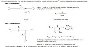
If you don't use a voltage follower between the sections, to get close to second-order Linkwitz-Riley, you would have to cascade sections with very different impedances. The first sections would need a resistance that's much smaller than the resistance in the second sections.
In the second sections, you would have to correct for the amplifier's input resistance in both the low pass and the high pass. That is, use the equation for R2 in both cases, not just for the high pass.
Do you know what impedance your signal source can drive without problems?
In the second sections, you would have to correct for the amplifier's input resistance in both the low pass and the high pass. That is, use the equation for R2 in both cases, not just for the high pass.
Do you know what impedance your signal source can drive without problems?
Can you drive headphones with those outputs and get a reasonable sound quality (neither excessive distortion nor lack of bass)? If so, then apparently you can drive the headphones' impedance.
Regarding the first paragraph of post 6:
If I understand you correctly, you want to make a second-order (i.e. 12 dB/octave) Linkwitz-Riley crossover filter that consists entirely of resistors and capacitors (a so-called passive RC filter), and you want to put that filter between the signal source and amplifiers that drive your loudspeakers. Please correct me if I got that wrong.
The thing is that in principle it is impossible to make a Linkwitz-Riley filter using only resistors and capacitors for reasons that are difficult to explain to anyone who hasn't had electric network theory classes. In fact most filter types require either inductors or amplifying devices (transistors, op-amps, tubes, whatever) in the filter circuit.
However, for the special case of a second-order Linkwitz-Riley filter, even though you can't make it with only resistors and capacitors, you can approximate it pretty well.
The way to approximate a second-order Linkwitz-Riley filter with only resistors and capacitors is to make two first-order RC sections, give the first a small R and a large C and the second a large R and a small C. The greater the resistance ratio between the first and second sections, the closer you can get to a true Linkwitz-Riley response.
Calling the resistance in the first section RA and the resistance in the second section RB, you get an error of a factor of 1/sqrt(1 + RA/RB) at the cut-off frequency when you optimize the values of the capacitors. When you make the RC products of the first and second sections equal to keep things simple, you get an error of 1/(1 + RA/(2 RB)), which is almost as good as 1/sqrt(1 + RA/RB).
Practical example: when RB is 4.1 times RA, the error at the cut-off frequency is just below 1 dB: 0.9994795 dB with equal RC products, 0.9478632 dB with optimized RC products.
So, to make a long story short: give the first section a resistance that is at least 4.1 times smaller than the resistance of the second section, adjust the capacitors such that the RC products of the sections are the same and you get within 1 dB of a Linkwitz-Riley response.
Last edited:
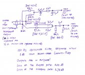
I designed a LR active filter last year.
This one is configured for 100Hz.
So first high pass filter is set to 150Hz (150%) and the second high pass filter is set to 75HZ (75%). Copy these components to a second stage and you have a full LR high pass filter with 360 degree phase shift.
On the low pass first filter is 75Hz( 75%) and second filter is set to 150Hz (150%) and second stage is a copy of the first to get full 360 degree phase shift.
You get a better Q by using offset filters.
You can scale the components to make your own filter and what ever frequency breakpoint you want.
See enclosed pdf file for the full circuit.
http://www.ckp-railways.talktalk.net/pdf2.pdf
Last edited:
Thanks guys,
You are exactly right, marceldevg, your 2nd paragraph is right on. Thanks nigelwright7557 but I don't want to use inductors and opamps - way to advanced for me. And yes, the over the ear headphones work nice with all three- phone, tablet and DOT.
I'm really not knowledgeable enough to understand the rest of what you wrote to build a circuit that you mention.
I may be asking too much but can you or anyone tell me what values of caps and resistors to get for the following circuit. I will be taking the headphone stereo output and place 1k resistors on each channel to make it a mono signal to be fed into a 2nd order circuit then into a tpa3110 amp with an input impedance of 14K to 36 K ohms (depends on the gain which I don't know so let's avg to 22K ohms:
Mono Left channel = line in circuit with high pass at 50 and low pass at 150 into amp and out to a 8 ohm woofer
Mono Right channel = Line in circuit with a 150 high pass - into amp and out to two 8ohm 3" full range =4 ohms
I appreciate the info from the previous "posters".
thanks
Thanks nigelwright7557 but I don't want to use inductors and opamps - way to advanced for me.
thanks
There are no inductors in the circuit, just resistors and capacitors.
The op amps are there to buffer the signal or there would be big losses.
You are going to lose a lot of your signal if you just use resistors and capacitors.
The beauty of the LR filter I offered is a fully balanced output around 100Hz.
Also the phase shift is always 360 degrees so no phasing problems.
I guess you could get away with one RC low pass filter and one RC high pass filter.
An externally hosted image should be here but it was not working when we last tested it.
Last edited:
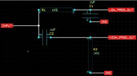
Thanks nigelwright for the circuit. I think I can handle that but the first one (75 and 150) was beyond me. Just to be sure, the circuit in the black image has the values for the left channel (50 hz high pass and 150 hz low pass) LINE IN to the amp that then goes to the woofer. Is that correct?
Thanks
Thanks
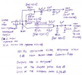
This is my version. It should be close to a second-order Linkwitz-Riley if I did the math correctly (and this time I was fully awake). At 150 Hz there is a dip of a bit less than 1 dB compared to a real Linkwitz-Riley.
I assume that the driving headphone output is low-ohmic, as it usually is on modern equipment with low supply voltages. I've assumed a 10 ohm output impedance, but whether it's 0, 10 or 20 ohm hardly makes any difference.
Some resistors have two values on the schematic. If you have resistors with E96 values at your disposal, you can use the values between brackets, these are slightly closer to what I calculated than the E12 values that are outside brackets. It doesn't make much of a difference, though.
The capacitors should be film capacitors. Polypropylene is best, but MKT is probably already good enough. Don't use class II ceramic capacitors.
Mind you, the outputs are in antiphase, so either the woofer or the two broadband speakers have to be connected inverted to correct for this. On top of that, the path from the woofer to your ears and from the broadband speakers to your ears should have nearly equal lengths (difference much less than a quarter wavelength at the crossover frequency, which means << 56 cm). If the paths are very different, using a Linkwitz-Riley makes little sense. You may then be better of with Nigel's first-order Butterworth filter.
The high-pass has 1.2 dB more loss than the low-pass. You can correct for this by setting different gains for the two amplifiers (I hope). Presumably you have to use different gain settings anyway because of sensitivity differences between the loudspeakers.
Attachments
Last edited:
Thanks Nigelwright for the time you spent on the circuit below.
Questions:
1. What does 1 and 2 mean on the 1uF caps? Should I use non-polarized ones?
2. I should know what 1K5 means on the resistors, but I don't - Is that 1000 ohm 5 watt?
3. I assume that this LINE IN 1st order butterworth circuit is for the mono signal coming in to the amp's left channel, with the high pass at 50 hz and the low pass at 150 hz. Could you find the time to show me the circuit going into the right mono amp channel (eventually into full range) with a high pass at 150 hz? If not, that's ok, but if you could answer questions 1 and 2, I would appreciate it.
Thanks
Attachments
Marcelvdg, you are really neat for giving such a detailed drawing - I hope one day to be knowledgeable enough to pay it forward to others. Thanks.
Questions I have about the paragraphs:
1. I have much higher fidelity systems so the system I'm building is really a nice background one, therefore, unless you tell me different, I will not use the E96 ones. Do you agree?
2. Since I'm using a tpa3100d2 amp's left and right channel, feeding both inputs with a mono signal, and using the left channel for the woofer and the right for twin full range, I thought I would put an Lpad (or two resistors (one parallel and one series) on the wire going to the paralleling of the twin full range (8 ohm per spk = 4 ohm.) Would either work OK?
Questions about the image below:
1. I think I didn't explain myself very well but I believe the circuit you drew will still work: Evaluating the circuit with my limited knowledge, I think the top filter applies to the woofer (low pass at 50 hz) and the bottom filter applies to the full range (150 HP). However, I'm using one amp with the left LINE input going to amplify the woofer with a low and high pass filter and the right LINE input going to amp the full range therefor, no stereo. In order to drive the woofer at a higher volume without exceeding its xmax, the top circuit will have a high pass (50 hz) filter circuit. Could all the work you did on the bottom circuit be added to the top somehow?
2. I'm assuming I can use the bottom circuit (150 HP) to go into the amp's right channel for the full range speakers?
3. What wattage should I use on the resistors and voltage on the (non-polarized I assume) caps?
4. About the first resistor on the left channel, is that a 10K 5 watt
5. about the first resistor on the right channel, I can't make that out
I know this is a lot of work and time for you, so I really thank you for helping.
scott
Attachments
Last edited:
Marcelvdg, you are really neat for giving such a detailed drawing - I hope one day to be knowledgeable enough to pay it forward to others. Thanks.
Questions I have about the paragraphs:
1. I have much higher fidelity systems so the system I'm building is really a nice background one, therefore, unless you tell me different, I will not use the E96 ones. Do you agree?
Yes, like I wrote it doesn't matter that much anyway.
2. Since I'm using a tpa3100d2 amp's left and right channel, feeding both inputs with a mono signal, and using the left channel for the woofer and the right for twin full range, I thought I would put an Lpad (or two resistors (one parallel and one series) on the wire going to the paralleling of the twin full range (8 ohm per spk = 4 ohm.) Would either work OK?
Yes, if the full range speakers are the ones that need attenuating.
Questions about the image below:
1. I think I didn't explain myself very well but I believe the circuit you drew will still work: Evaluating the circuit with my limited knowledge, I think the top filter applies to the woofer (low pass at 50 hz) and the bottom filter applies to the full range (150 HP). However, I'm using one amp with the left LINE input going to amplify the woofer with a low and high pass filter and the right LINE input going to amp the full range therefor, no stereo. In order to drive the woofer at a higher volume without exceeding its xmax, the top circuit will have a high pass (50 hz) filter circuit. Could all the work you did on the bottom circuit be added to the top somehow?
I simply forgot to mention that I didn't include the high pass, only the 150 Hz close-to-Linkwitz-Riley crossover. Given the constraints of only using resistors and capacitors, the best way to add a high-pass is to add a 100 nF or 220 nF film capacitor between the output of the low-pass section and the amplifier. If the amplifier is used in gain setting 00 at high volumes, use 100 nF, otherwise use 220 nF (see pages 21 and 22 of http://www.ti.com/lit/ds/symlink/tpa3100d2.pdf ).
(While I recommend film capacitors, TI recommends ceramic capacitors for the input coupling capacitors. The reason is simply that they try to keep the application costs down to the bare minimum. Even the cheapest of film capacitors are far better than class-II ceramic capacitors, but a few cents extra is often unacceptable in consumer equipment.)
Do you often play church organ or synthesizer music at high volumes?
2. I'm assuming I can use the bottom circuit (150 HP) to go into the amp's right channel for the full range speakers?
Yes, that's what it is meant for.
3. What wattage should I use on the resistors and voltage on the (non-polarized I assume) caps?
1 W for the 47 ohm resistors and 1/4 W for all other resistors should do fine, even with a fairly powerful headphone output. I recommend polypropylene or MKT film capacitors; these normally have working voltages of 50 V or higher, which is much more than needed and should work fine.
4. About the first resistor on the left channel, is that a 10K 5 watt
5. about the first resistor on the right channel, I can't make that out
If you mean the resistors to ground, 10 kohm 1/4 W for both left and right.
I know this is a lot of work and time for you, so I really thank you for helping.
scott
Thank you for giving me something interesting to do during the long and boring train journeys I made yesterday and today!
Last edited:
- Status
- This old topic is closed. If you want to reopen this topic, contact a moderator using the "Report Post" button.
- Home
- Source & Line
- Digital Line Level
- Linkwitz-Riley 12 db line level calculation