They compete on dynamic range and SINAD numbers measured with sine waves of 0 dBFS and less. Taking headroom reduces those numbers. I think a user-settable input attenuator (preferably with clipping indicator) would be a good solution, though.
Another issue is that the person who defines the specs is usually not the same person as the one who designs the circuit. It could well be that the marketers who set the specs have no clue about intersample overs, or simply don't care as long as their customers don't complain.
Another issue is that the person who defines the specs is usually not the same person as the one who designs the circuit. It could well be that the marketers who set the specs have no clue about intersample overs, or simply don't care as long as their customers don't complain.
So much modern stuff is unlistenable imo/ime because of normalising to 0dBfs or close to.
Switchable in/out and switchable absolute polaritry and you're on a winner.
Dan.
If you don't mind hearing a click when you switch over, the circuit in post 1 can be switched in/out with a switch to ground and a pull-up resistor connected to the active-low set input of the second flip-flop in the bottom row. Changing absolute polarity can be done with an EXOR in the data line, if you don't care about the 1 LSB offset that gives you.
In fact you could use an 74AHC86 quad EXOR as polarity changer, clock buffer and delay circuit to prevent hold time issues.
Last edited:
Marketeers do not set the specs. Entities like the EBU and the SMPTE do.
That's only true for specs that are standardized, like interface standards, not for performance parameters such as dynamic range or for things related to cost.
That's only true for specs that are standardized, like interface standards,
Such entities cover a little more than just interface standards.
not for performance parameters such as dynamic range or for things related to cost.
Those aren't specifications. They are performance requirements and the factors that govern them are varied but I doubt those who design,make and market the equipment ever get a look in. Can't say I ever saw a marketing representative of Neve or PMC calling the shots in a suite. Unless, that is, by marketeer you mean those more traditionally known as clients.
As an integrated circuit designer I'm used to getting lists of requirements I need to meet, and usually there is a header "Specifications" above the list. It could be that that's sloppy language, but it is the terminology I'm used to.
Sometimes the specifications or whatever you call them come straight from a customer, sometimes they are the result of negotiations between potential customers and a marketing department, sometimes they come from some international standard, sometimes they are derived specs that were derived from a system spec by a system designer.
Anyway, it seems that this is a semantic rather than a technical discussion.
Another solution to intersample peaks
I have been wanting to swap an AK4413 dac chip with an AK4414. This is a 32 bit chip replacing a 24 bit.
Read and reread the data sheets and it is 50 pages of identical specs and graphs. Using as a four channel dac so not parallel.
The current chip is almost the same specs. Only THD is better, the graphs showing THD vs freq with different decoupling on Vref. The AK4414 has 2 - 3 dB lower THD.
My original reason for installing a 32 bit chip was to get more bits for digital attenuation. But it looks like the date is LSB justified. Or there would be 8 zero buts in front of the signal. An additional 48 dB of digital headroom.
I still want to swap out these dac chips. This is a 12 dollar part.
With this change yield headroom for intersample clipping, 8 more bits for attenuation, or a just the potential for a couple dB reduction in THD?
This is a 10 euro tweak also.
Another solution to intersample peaks
I have been wanting to swap an AK4413 dac chip with an AK4414. This is a 32 bit chip replacing a 24 bit.
Read and reread the data sheets and it is 50 pages of identical specs and graphs. Using as a four channel dac so not parallel.
The current chip is almost the same specs. Only THD is better, the graphs showing THD vs freq with different decoupling on Vref. The AK4414 has 2 - 3 dB lower THD.
My original reason for installing a 32 bit chip was to get more bits for digital attenuation. But it looks like the date is LSB justified. Or there would be 8 zero buts in front of the signal. An additional 48 dB of digital headroom.
I still want to swap out these dac chips. This is a 12 dollar part.
Will this change yield headroom for intersample clipping, 8 more bits for attenuation, or a just the potential for a couple dB reduction in THD?
This is a 10 euro tweak also.
Last edited:
I don't know these chips but in general, the advantages of a 32 bit interface as compared to a 24 bit interface are that a chip with a larger word length sells better and that the quantization error is smaller. In most cases the quantization error will already be negligible with 24 bits, though.
A digital attenuator solves the intersample clipping problem when the signal first passes through the digital attenuator before going into any type of filter (interpolation, ASRC, whatever) and the attenuation is high enough. A few dB is usually enough, 48 dB will only cost you much more signal to noise ratio than necessary.
A digital attenuator solves the intersample clipping problem when the signal first passes through the digital attenuator before going into any type of filter (interpolation, ASRC, whatever) and the attenuation is high enough. A few dB is usually enough, 48 dB will only cost you much more signal to noise ratio than necessary.
Thanks for the feedback. Project gets pushed again. Only advantage I can see if the slight improvement in THD.
Using the digital attenuator does present the new to me (1 year) overload issue. Even if the data is MSB justified in the chip the attenuator is on the front end. So no additional bits to be thrown away for volume control.
Plus the used interface I was watching for this project sold for more than worth to me. I am not going to butcher mine any further especially a 44 pin chip swap.
If you don't mind hearing a click when you switch over, the circuit in post 1 can be switched in/out with a switch to ground and a pull-up resistor connected to the active-low set input of the second flip-flop in the bottom row. Changing absolute polarity can be done with an EXOR in the data line, if you don't care about the 1 LSB offset that gives you.
In fact you could use an 74AHC86 quad EXOR as polarity changer, clock buffer and delay circuit to prevent hold time issues.
I made a stupid mistake, I meant the active-low set input of the third flip-flop in the row that starts with LRCK.
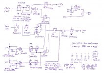
Taking into account all comments in this thread, I came up with this improved version (also neither tried nor tested). The capacitance on the clock line is reduced by using two octal flip-flops where all eight units have only one common clock input. The switches allow one to switch on and off the attenuation and to invert or not invert the signal, switching between modes is always done at the start of a new word.
The input has a 1 ns hold time requirement, which is not in accordance with the 0 ns required by the I2S standard (property of the SN74AHC273, most other AHC flip-flops are worse). This will usually not be a problem, but when it is, it can be solved by delaying the LRCK and data signals with an RC filter.
The input has a 1 ns hold time requirement, which is not in accordance with the 0 ns required by the I2S standard (property of the SN74AHC273, most other AHC flip-flops are worse). This will usually not be a problem, but when it is, it can be solved by delaying the LRCK and data signals with an RC filter.
Attachments
- Status
- This old topic is closed. If you want to reopen this topic, contact a moderator using the "Report Post" button.
- Home
- Source & Line
- Digital Line Level
- Solving the intersample DAC clipping problem for about ten euros