I was searching for a good DAC at a reasonable price tired of my computers sound card. It was not easy for me, as I have no experience with external DACs. Opened a thread to ask for help. Thanks to community (special thanks to abraxalito) decided not to make shortcut and ordered this chinese DAC based on 16 TDA1543's and CM6631 USB interface board.
Out of the box SQ was surprisingly bad, one channel was very noisy. And there was almost no lows. Removing the output coupling caps fairly improved it (my amp already have them). 2014 Macbook did not want to make a friend with it and showed "no output device". Next day I have decided to change the sampling rate on Win7 audio settings from 192kHz to 96kHz, noise is all gone. It was much cleaner at the bottom end, highs were detailed.
Here I am going to ask for guidance and share my thoughts on modification results.
Sorry for the quality of images, it was night time after hard work day.
Attachments
Last edited:
NOS 1543 DAC is very potent if built correctly. Dont really know what voltages those chinese dacs are running but I have built a DAC with 8x1543 and with 8V VDD and biased as adviced on this site: DDDAC 2000 There you can find a lot of "know-how" about the TDA1543 chip, highky recommended.
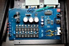
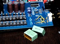
Here's mine with part-finished mods
First mods I'd suggest are to delete the blue 2n2s and the yellow '3K's right at the output.
Next up - switch off the internal current sources (make pin7s all unconnected) and build a pair of discrete current sources as pull-ups to the positive supply rail.
Add series inductors and extra caps (on the perpendicular board) prior to the regulator to improve ripple rejection.
Attachments
Ok thks for the help i will start the modsFirst mods I'd suggest are to delete the blue 2n2s and the yellow '3K's right at the output.
Next up - switch off the internal current sources (make pin7s all unconnected) and build a pair of discrete current sources as pull-ups to the positive supply rail.
Add series inductors and extra caps (on the perpendicular board) prior to the regulator to improve ripple rejection.
Tks i will check it.NOS 1543 DAC is very potent if built correctly. Dont really know what voltages those chinese dacs are running but I have built a DAC with 8x1543 and with 8V VDD and biased as adviced on this site: DDDAC 2000 There you can find a lot of "know-how" about the TDA1543 chip, highky recommended.
The big green caps stays? (In my case white)First mods I'd suggest are to delete the blue 2n2s and the yellow '3K's right at the output.
Next up - switch off the internal current sources (make pin7s all unconnected) and build a pair of discrete current sources as pull-ups to the positive supply rail.
Add series inductors and extra caps (on the perpendicular board) prior to the regulator to improve ripple rejection.
And the two resistors?
Where is the I/V resistor on this DAC? (I don't own one, just looking at the pics.)
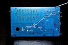
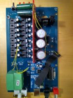
At any rate - it looks like those 16 tda1543 chips are in sockets. You might try experimenting with removing some of them, to see if you like the sound better with fewer chips. But pulling chips also serves as a useful debugging step.
But if you start pulling tda1543 chips, you'll have to adjust the I/V resistor accordingly.
I can't tell from the pictures how clean the soldering job is. In my own tda1387 project, I did a sloppy soldering job and created several solder bridges. The results of the solder bridges ranged from total noise output, to more subtle noise...
There was one solder bridge that I could not see with my eye at all, but it was there. I could infer it by using my DMM and comparing resistance between tda1387 chip pins. The readings across two pins on one tda1387 was different than all its peers. I actually completely re-soldered that chip twice before I got it to read the same as the others; and in the process, that removed some audible noise that was coming through.
That's why I was suggesting pulling the tda1543 chips. Maybe one of the sockets is soldered poorly. The tda1543 chips are no longer made, so who knows where the manufacturer is getting their stock. I'd say there's a non-zero chance you could have a bum chip in that 16x array.
Or you can also do like I did, and just look at the resistance between chip pins. The resistance between pin X and Y should be roughly the same for each chip I believe. It's a slow and painstaking process, especially with 16 chips! But it's also easy, and doesn't require any soldering.
Where is the I/V resistor on this DAC? (I don't own one, just looking at the pics.)
Hi Matt - I just buzzed mine out to double check and the I/V resistors are the two marked '140' between the DAC chips and the large output caps. The 2n2s are in parallel with them.
But if you start pulling tda1543 chips, you'll have to adjust the I/V resistor accordingly.
I discovered something strange when I got into checking the I/V resistor's value. The power supply reg (LM317T fitted to mine, not the higher current LM338 as shown on silkscreen) has 270ohm and 1k for the voltage setting. This makes for a supply about 5.9V so the output compliance range for the DAC should be from +1.8V to +4.7V or 2.9V p-p (~1VRMS). With 140ohm for I/V this entails a current of almost 21mA but an array of 16 chips should give a total current of 16*2.3 = 37mA. I did not ever see any clipping on the analog output waveform though.
From poking around with my scope it looks like the digital format output from the S/PDIF receiver is resulting in only 15 useful bits reaching the DAC chips. I plan to fix this by some means - adding a flip flop for a 1CLK delay is one possibility.
I can't tell from the pictures how clean the soldering job is. In my own tda1387 project, I did a sloppy soldering job and created several solder bridges. The results of the solder bridges ranged from total noise output, to more subtle noise...
Mine looks hand-soldered to me and the soldering quality isn't wonderful. Too much solder is used on the SMT parts but the through-hole soldering is good.
Keep the big caps if your amp or preamp doesn't have input capacitors. If you mean the two '140' resistors then yeah, they stay.
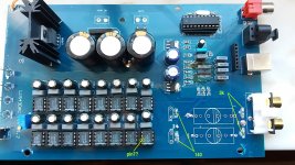
ok caps removed.... (i will bridge with wire the big ones)
theres is a 3k resistor also beneath yellow caps... remove also???
next:
pin7, what do i do with it??? lift from socket? or is from the bottom of the board that i have to do the surgery?
thanks
Attachments
I brought my another laptop from work to home that runs Windows 10. It has immediately detected the driver when I pluged the USB cable. After playing just few seconds I could not believe my ears. It is nothing comparable with my older laptop. I never thought that SQ so heavily depends on digital source. Now there is another problem, it has random punchy clicks sometimes. Strangely when I play music directly from its output same thing happens. Internal DAC also suffers from the same problem.
I made it. But I am not quite sure how to do with discrete current source and pin7s. Currently studying different designs.First mods I'd suggest are to delete the blue 2n2s and the yellow '3K's right at the output.
About the 3k resistors - yes remove them. They'd slipped under my radar, I need to remove mine too
On pin7, I found its sufficient just to pull out the blue multiturn preset pot - behind the source selector button.
Thanks Abraxalito
")
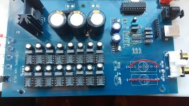
done...
next, what i need to do???
Attachments
I brought my another laptop from work to home that runs Windows 10. It has immediately detected the driver when I pluged the USB cable. After playing just few seconds I could not believe my ears. It is nothing comparable with my older laptop. I never thought that SQ so heavily depends on digital source. Now there is another problem, it has random punchy clicks sometimes. Strangely when I play music directly from its output same thing happens. Internal DAC also suffers from the same problem.
Given you've the same issue from both the Taobao and the internal DAC this sounds like a Windows latency problem to me. You can find some online checker for DPC latency I believe though on a laptop I've no idea how you can reduce it.
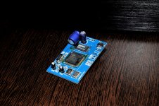
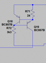
I use the standard two-transistor version - attached.I made it. But I am not quite sure how to do with discrete current source and pin7s. Currently studying different designs.
@pistollero : You'll need a couple of current sources like the picture I'm showing here, one for each channel. The 24ohm resistor sets the current, its just a rough guess at present for the value you'll need. The 3k3 resistor goes to 0V, the top rail is the DAC's +5.9V supply.
Attachments
Last edited:
Given you've the same issue from both the Taobao and the internal DAC this sounds like a Windows latency problem to me. You can find some online checker for DPC latency I believe though on a laptop I've no idea how you can reduce it.
I use the standard two-transistor version - attached.
@pistollero : You'll need a couple of current sources like the picture I'm showing here, one for each channel. The 24ohm resistor sets the current, its just a rough guess at present for the value you'll need. The 3k3 resistor goes to 0V, the top rail is the DAC's +5.9V supply.
ths
is this correct??
Attachments
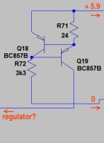
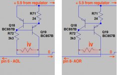
Yes, that's the idea - the output you've marked 'regulator' goes to pin6 (and the other channel, pin8) of the TDA1543As. The I/V resistor goes between that output pin and 0V, which is the same configuration as its shipped in. So no need to change anything there.
ok... but í´m a little confused....
is this??? correct??
Attachments
- Status
- This old topic is closed. If you want to reopen this topic, contact a moderator using the "Report Post" button.
- Home
- Source & Line
- Digital Line Level
- Chinese 16x TDA1543 DAC modification