...from what I understand the capacitors and resistors are already good enough.
What do you mean by that? What is your understanding on that?
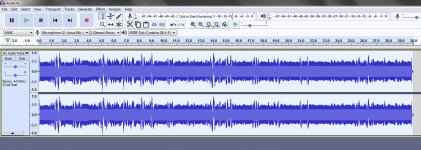
In an effort to try to get a clearer impression of the sound my board is producing, I generated a continuous sine wave tone in Audacity:
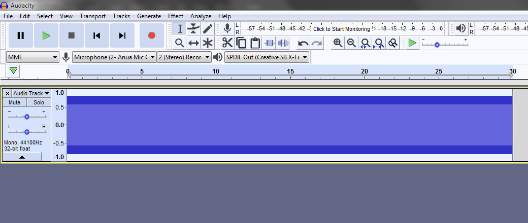
I then played this tone and recorded what it sounded like through my existing hifi setup using the DAC in my Yamaha DSP-E800 using my Auna CM-600 condenser microphone:
You can hear the sound recording here:
01.wav - Google Drive
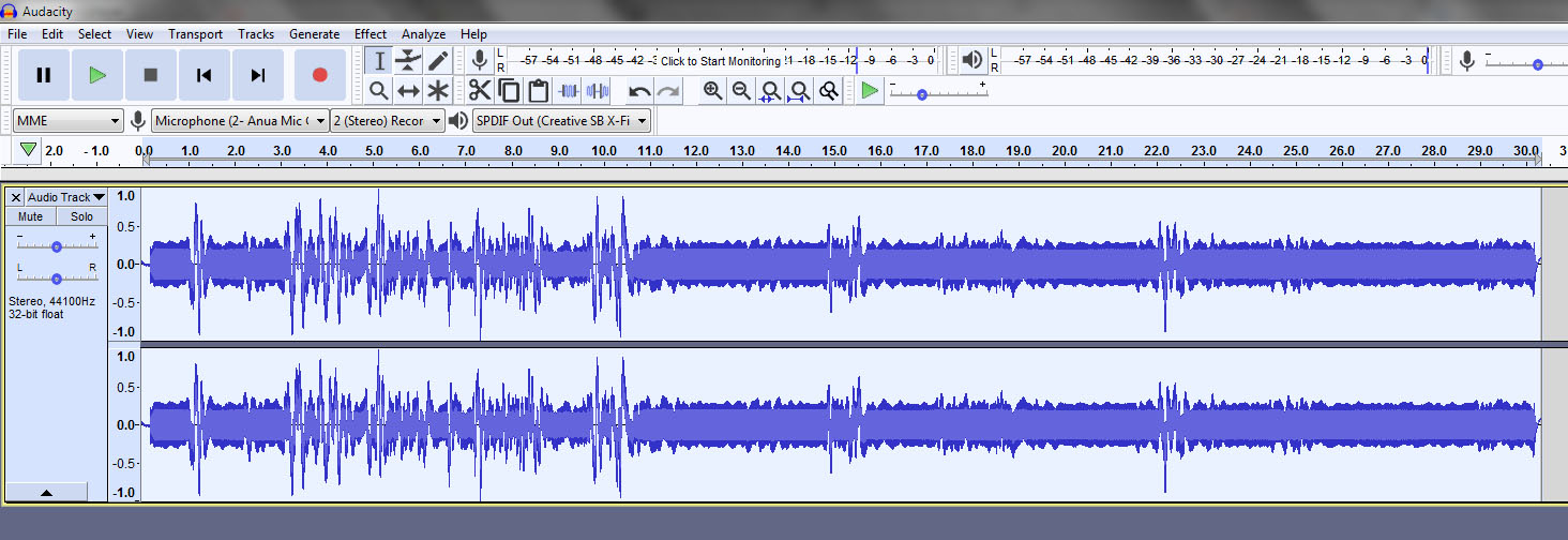
I then hooked up my ESS board instead of the Yamaha's DAC and repeated the process and got this:

You can hear the sound recording here:
02.wav - Google Drive
The first thing that is immediately obvious is the large change in pitch, the ESS is much higher pitched, indicating there are no low frequencies. You can hear the distortion too, the tone sounds modulated.
I performed this test using a battery to power the ESS board, to give it a nice, clean DC source and eliminate the PSU as the source of issues.
I am really kicking myself for not listening to the ESS board in it's virgin, unmolested state as I'm having a hard time believing it could possibly sound this bad.
It seems clear to me that my board has a serious issue and I don't know if I introduced the issue by messing up the replacement of a cap or if it sounded like this before anything was done to it.
I guess there's not much else I can do other than attempt to improve the SQ, but it's looking to me like my best bet is to put this board to one side, get one of the better quality green ones and start over, with the very first step being the one I missed first time around - to listen to the board in it's original, unmodded state.
I then played this tone and recorded what it sounded like through my existing hifi setup using the DAC in my Yamaha DSP-E800 using my Auna CM-600 condenser microphone:
You can hear the sound recording here:
01.wav - Google Drive
I then hooked up my ESS board instead of the Yamaha's DAC and repeated the process and got this:
You can hear the sound recording here:
02.wav - Google Drive
The first thing that is immediately obvious is the large change in pitch, the ESS is much higher pitched, indicating there are no low frequencies. You can hear the distortion too, the tone sounds modulated.
I performed this test using a battery to power the ESS board, to give it a nice, clean DC source and eliminate the PSU as the source of issues.
I am really kicking myself for not listening to the ESS board in it's virgin, unmolested state as I'm having a hard time believing it could possibly sound this bad.
It seems clear to me that my board has a serious issue and I don't know if I introduced the issue by messing up the replacement of a cap or if it sounded like this before anything was done to it.
I guess there's not much else I can do other than attempt to improve the SQ, but it's looking to me like my best bet is to put this board to one side, get one of the better quality green ones and start over, with the very first step being the one I missed first time around - to listen to the board in it's original, unmodded state.
Attachments
Ian, The DAC recording is louder than the first recording. The second one might be clipping somewhere. It sounds distorted, which mean more high frequencies are created by the distortion process. Relatively speaking, that makes it sound like there is less bass. Don't confuse more highs for less lows. Make sure levels are the same and not clipped. Best to turn down the digital signal going into the DAC by 3.5dB then add a volume pot to the DAC and adjust it up and down to make sure it sounds the same at all volumes and not worse at higher volumes which might mean clipping somewhere.
Also, expand out the time axis in Audacity until you can see the waveform for one cycle of the audio tone. It should look like a sine wave like you would see on an oscilloscope. If you have the time axis too compressed you can get aliasing in the visual depiction of the waveform.
Also, expand out the time axis in Audacity until you can see the waveform for one cycle of the audio tone. It should look like a sine wave like you would see on an oscilloscope. If you have the time axis too compressed you can get aliasing in the visual depiction of the waveform.
Last edited:
I equalised the volume of the recordings in Audacity because the ESS one was a lot quieter. I'm pretty sure there is no clipping.
I'm also pretty sure there is no bass because when I listen to music through the ESS board, there is no bass at all, just a lot of treble and some midrange.
I can do another test and modify how I do it if you think this one is flawed, I'm not at all experienced at audio testing so I'm more than happy to be guided.
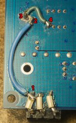
Here's the current state of my board:

I had to scrape away the ground plane around 3 (the cap's negative pin) because it was shorting to ground. I then directly connected this pin to 4, which is pin 8 of the op amp. As far as I can tell, the only SMD parts I have bypassed by doing this is a single tantalum capacitor.
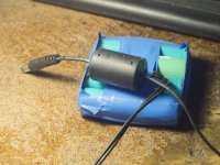
Here's the simple battery pack I quickly threw together from four Samsung 18650 cells:

I'm also pretty sure there is no bass because when I listen to music through the ESS board, there is no bass at all, just a lot of treble and some midrange.
I can do another test and modify how I do it if you think this one is flawed, I'm not at all experienced at audio testing so I'm more than happy to be guided.
Here's the current state of my board:
I had to scrape away the ground plane around 3 (the cap's negative pin) because it was shorting to ground. I then directly connected this pin to 4, which is pin 8 of the op amp. As far as I can tell, the only SMD parts I have bypassed by doing this is a single tantalum capacitor.
Here's the simple battery pack I quickly threw together from four Samsung 18650 cells:
Attachments
Ian... I can say only what a xxxx are you doing.
You are like a butcher not someone with electronic skills. Sorry for hard word. But your posts are cuting down nice fluently progress of this thread. It is normal that noone want to help you.
First unplug power supply.. Pull out opamp. Connect 12v to dac and lets go to work. Put gnd probe on gnd pin and measure all 8 pins on opamp socket....WITHOUT OPAMP!!! Turn the multimeter to 20v Dc position.
First connect green wire to blue one. Now you can have pin 8(4) connected from cap to pin on top route and under with green to cap what is gnd and you have short circuit. Or at least cut or unsolder green wire away. It is uuugly soldered to opamp pin... Thinny part is maybe touching next pin.
Mark4. We are waiting to Katana review. Thank you for all your explanations in this thread.
Last edited:
Regarding Katana review, finally just got it working today. I am supposed to leave it playing for 3-days to settle in. Also, there is some ongoing communication with Allo about the test setup I am using, etc. So, probably need to give it a little more time, but I'm working on it.
I will butt out for today if possible if there is someone to help Ian. He needs to get some smaller gauge wire for sure. Ian: you can get little 30 gauge wire wrap wire at Amazon or an electronics supply house. Amazon also has 22 gauge hookup wire. Using big fat wire for little circuit board connections is not really appropriate. Please take a look at all the pictures in the thread to see what other people are doing. We aren't working on a car or a guitar amp here. It's tiny stuff.
I will butt out for today if possible if there is someone to help Ian. He needs to get some smaller gauge wire for sure. Ian: you can get little 30 gauge wire wrap wire at Amazon or an electronics supply house. Amazon also has 22 gauge hookup wire. Using big fat wire for little circuit board connections is not really appropriate. Please take a look at all the pictures in the thread to see what other people are doing. We aren't working on a car or a guitar amp here. It's tiny stuff.
Last edited:
Okay, clearly my lack of skills in working with tiny electronics is annoying people and four of you have told me I've ruined your thread, so I'll leave you to it, my apologies for the interruption.
I thought I could learn as I went along, but obviously, if you don't already have skills and experience then you will just aggravate people here.
I thought I could learn as I went along, but obviously, if you don't already have skills and experience then you will just aggravate people here.
Ian, please take it easy. You are welcome here. You are just a beginner at this type of work whereas some of the people here are very experienced. You have no idea what kind of expertise is lurking around here. Anyway, so long as you are willing to take good advice when it is offered and you try to keep learning and making progress you are welcome here. I think its more some of the more experienced guys don't know what to say to you or how to explain things that seem very basic to an expert. So, you get some expressions of frustration from people, I think that's all. They experience emotions just as you do, after all, we are all human. Right? So, get some smaller wire, try to make you work look neat and careful and ask questions about things you are unfamiliar with. You may be very smart in the world you inhabit and compared to the people you normally work with, but you are in a bigger league now being here. Here you are a beginner, but at one time everybody else was in the same position. This forum is visited and read by people all over the world. Some of the people here have PhDs in electronics, have been corporate VPs of engineering, etc. So, all I can say is keep trying and you will learn a lot and hopefully end up with a very nice DAC. You may end up ruining the one you have now even if it isn't ruined yet, but this is new to you. I'm sure other people have already ruined stuff long ago and are past that now. You, not so much yet. Just don't give up. Quitters get the least respect of all.
What do you mean by that? What is your understanding on that?
I actually concluded that from your posts, at some point you said that the real differences come with current to voltage conversion and changing capacitors will not do much.
As im not that good at circuit making, is there something ready for current to voltage conversion?
would something like that do?
Current To Voltage I/V Conversion Photoelectric Signal Amplifier Module Emitter | eBay
For those who want to try the real time pcm to dsd conversion in foobar2000:
Foobar 2000 for Dummies (Part 1) – General Setup | DIY-Audio-Heaven
Foobar 2000 for Dummies (Part 2) – Playing DSD – New SACD plugin (0.9.x and 1.x.x Series) | DIY-Audio-Heaven
Foobar 2000 for Dummies (Part 3) – Playing DSD – Old SACD plugin (0.8.x and 0.7.x series) | DIY-Audio-Heaven
There are plenty of custom DSD filters to select, 4 different algorithms to convert PCM to DSD based on Philips ProTech tools.
For me there is no need to rely on hardware up-sampling if you are using only audio files on a pc, through spdif or i2s over usb or whatever.
note if connecting to DACs: spdif limit DSD64 (DoP), DSD128+ only over i2s
have fun..
Last edited:
I actually concluded that from your posts, at some point you said that the real differences come with current to voltage conversion and changing capacitors will not do much.
Relatively speaking, changing a few caps won't do much. But, using the right passive components to fabricate I/V and differential stages is important and that point is made by ESS in their documentation.
Of course, the first thing people want to know is, what cheap (or expensive) ebay board will work at least well-enough for upgrading the DAC? For power supplies, there may be a few. Other than that, the answer is none, you have to build it yourself. I have given you pictures of one way of doing it. The schematic for what I did is given in this thread. Information about power supplies and bypassing, its all there.
Basically, that's all there is. Some examples and some advice, but its not be organized as a beginner or kit type of project. One reason for that is when starting out there was no way of knowing what exact architecture would win out. We are only now getting pretty close to the end of knowing everything we need to know to get the support circuitry around the dac chip good enough that we are probably getting back to the point where the dac chip may be the weak link, but we are not quite all the way there yet, IMHO.
Last edited:
Regarding software or hardware upsampling, the only thing I can say is that not all upsamplers are the same. A result, some sound a lot better than others. My recommendations are only for things that I have tried and found to work well. In particular, there are no software upsamplers I am recommending at this time.
Pretty soon I hope to test out the new lower cost AK4317 board from ebay. I may do some mods on it to improve signal integrity for the I/O interconnections. The reason the new board is lower cost is because it is PCM/I2S/DSD input only. There are no SPDIF, TOSLINK, or AES inputs. Assuming it works as well or better than the other AK4317 board with the ES9038Q2M DAC, it would be suitable for those folks using Amanero or XMOS USB boards, and who do not need other types of inputs.
In addition, in order to get very high sample rate PCM/DSD to work with the DAC board I had to modify the board with more ground pins and wire the PCM/DSD interconnection cabling to reduce jitter and ground bounce, and to improve high speed reliability. I will see I if can find the post with pictures of how to do that. Presumably, the same kinds of issues would be likely to occur with an Amanero or XMOS board at the highest sample rates.
EDIT: Pictures of improved PCM/I2S/DSD interconnections: http://www.diyaudio.com/forums/digital-line-level/314935-es9038q2m-board-144.html#post5457773
Last edited:
Regarding the promised Allo Katana review, looks like it may be a little delayed. While testing here found something that could affect playback sound quality. Asked Allo about it and after a little of their own testing they apparently found I was onto something. Received a follow up email from them asking that reviewer testing be suspended until further notice, although they said they do not think it will take very long before notice will come. Anyway, nothing I can do about giving folks here a timely review until I get the go ahead from Allo to continue.
I read this on the allo katana thread yesterday
")
You're the sherlock holmes of diyaudio!
I'm waiting for a new clock for my board
http://www.crystek.com/crystal/spec-sheets/clock/CCHD-575.pdf
In your pictures, your new clock reads CCHD-975-90, but I can't find this model.
As I am going to do soldering job on the board, do you think Some caps replacements could help SQ?
I know that the big improvement mod is the I/V stage but it is beyond my skills for now. I will try to find some help from a friend, cause I will need a real 'step by step' tutorial for this mod.
I already installed low noise psu dual rail and LT3045-78xx 3.3v regulator and I changed the opamp.
So, after the clock replacement, What may I (try to) do to improve SQ?
btw, Thank you Mark and all the others 'pros' for the knowledge you gave from the start of this thread last December.
In your pictures, your new clock reads CCHD-975-90,
... btw, Thank you Mark and all the others 'pros' for the knowledge you gave from the start of this thread last December.
The clock I have is a CCHD-575-100-50. That's 100MHz, 50ppm.
You and all those who have thanked me for my contributions to the thread are all quite welcome. My goal has been to try to help people make better DACs without needing access to expensive specialized test equipment and through learning more about how DACs and electronics in general work.
Regarding an I/V stage, I think Mikett posted some pictures of his I/V stage for this DAC before he had a mishap with the DAC board and went on to something else. Anyway, Mike's I/V stage wasn't nearly so tiny as the one I did. IIRC, he used some copper foil in places to help with making some ground plane on his I/V board. Maybe if Mike would be so good so as to re-post pictures of that it might look easier to build than what I did.
Somehow or other we need to find some way for people to be able to build an I/V stage that isn't too daunting to take on as a project. That, and a proper AVCC supply are really essential for good SQ results.
@terry22, Found pictures of Mikett's I/V and AVCC board. Hopefully, that may look more practical to implement?
http://www.diyaudio.com/forums/digital-line-level/314935-es9038q2m-board-111.html#post5436895
Although, the board Mike did is not unreasonable in size, I would like to see some of the critical wires be shorter, such as for AVCC and ground. I think I may have mentioned to Mike back then that mounting his board on the bottom of the DAC board rather than the top might be one way to help keep the wiring very short, low resistance and low inductance, and to maintain small loop areas.
Last edited:
Hi guys
My board was a diversion from me towards the 3 op amp IV stage. Once I realized it looked easy I wanted to see how a one op amp solution would sound to the 3 op amp IV. Well as you know it did not come to pass.
However since that time, I had suspected that the 1 op amp solution posted by ESS has an error in the biasing of the output stage. I am not knowledgeable enough to determine what the error was but abraxalito pointed out the error AFTER I found out there was something fishy in the output. ES9038Q2M Board
That would explain the output voltages I was getting. Always check the output before hooking up everything.
Prior to that I had begun laying out the addition using out the 3 op amp stage. Since then all this is laying there since the 9038Q2M board is no more.
One key reason why I had placed the board above was because thoughout the project my eyes were firmly affixed to how I could fit this into a case. As I started cobbling bits and pieces I started to realize the end result may not fit nicely into a case.
So when I put the DAC project into RESET I started off with something that I already knew what I needed it to do and what modifications I wanted to do. So I went into a 9028 PRO board instead.
Moving from 9038Q2M to a 9028Pro board
About removing the LT317/337 I am going to put them back in as I will be using them as preregulators only and will cut the traces to divert to the SuperRegulator Power Supply. I will be able to get all of this into a case dedicated to this DAC board. Except that I will be mounting my EMI filter and transformers in another remote case. Only low voltage AC will be coming into the DAC case.
Even replacing the clock is easy on the 9028 board as there should be pads ready to accept them as shown in posting #108
Last edited:
- Home
- Source & Line
- Digital Line Level
- ES9038Q2M Board