I haven't failed to show respect and I'm doing my best to learn. Try to remember a time when you were not so well informed on the subject and how you had to learn.
I was being told 'do it this way' and all I was doing was resisting making the decision to go that way until I had learned why that was the best way, if you find this disrespectful then we will simply have to agree to disagree.
My approach is to be thorough in exploring different options before finalising a design decision, which is how I was taught to approach a problem, if this upsets some people then they should be less easily upset, quite frankly.
Last edited:
Dear Ian...
No point wasting effort. Maybe best just to add to the ignore list. There seems to be more going on here than than we fully understand, so probably best to be patient and not give it much attention in the meantime.
Also, no reason to stop everything else we might be talking about. Is anybody still waiting for parts or actively modding these DACs, or are we kind of getting to a point where people mostly have gotten out of the thread whatever there is to get one of these Chinese DACs into tiptop shape?
There is only one thing I am still actively interested in investigating more that could be applicable to ES9038Q2M and that is outboard interpolation filtering. Problem is it takes a Sharc chip to do it, and the software development system for Sharc chips is not free. If one buys a Sharc development board then it comes with, I think, a 3-month 1-seat software development system license. Personally, I don't know enough yet about what I might want to do to consider starting the clock ticking. I did get a little ADAU1452 to play around with since the software for that doesn't expire. But, it is no where near fast enough for outboard interpolation filtering. Still pretty early in the learning curve for it too, so it may be awhile before much more to say on that.
Other than that though, if others are interested in doing more with Q2M such as master mode I2S, with ASRC on or off, I would be happy to help with software and advice, but not much curiosity about it at this point myself.
Last edited:
No point wasting effort. Maybe best just to add to the ignore list. There seems to be more going on here than than we fully understand, so probably best to be patient and not give it much attention in the meantime.
Have I really done something so bad that this guy's ego has been bruised so badly that not only does he not want to help me, but he now seems to want to try to stop anyone else from helping me either?
Ian, even though you are on my ignore list I can still read your posts if I choose to. Just so you know, I was not trying to prevent to you from getting help. I was trying to suggest to eziitis to not let you aggravate him if he does in fact find you aggravating. As far as you getting help, I'm sure if you ask for help somebody will step up to help you.
Here is a discussion on DACs, in particular the I/V stages that includes John Siau, the VP of Benchmark Systems and which I found rather informative:
DAC IV stages
DAC IV stages
Interesting link, thanks.
One thing which caught my eye there and which looks to differ from ESS's own recommended circuits is this, written by John Siau :
One complication is that high-frequency switching noise is always present on the current outputs of sigma-delta converters. This high-frequency noise must be bypassed with rather large NPO or COG capacitors before entering the I-V converter.
Mark have you looked at the internal circuits of your DAC3 to notice the large NP0 cap right next to the DAC chip? Could this be a part of the reason why DAC3 has sounded better than your designs based on ESS's recommendations?
<afterthought> Do you have a link to Bruno's thinking about what people can hear you've referred to in your post directly under this one?
Oh and a useful link pertaining to ESS DAC common-mode noise (referred to by Mr Siau) : Hi-end DSP based multi-channel integrated Preamp/Crossover/DAC project
Last edited:
John Siau designs some of the best DACs in the world, but IMHO he is wrong about some aspects of human aural perception. Not really his fault, I guess. Not his area of expertise. Let's get him and Jakob2 together, would probably be a good idea. I would like to be in on that conversation as well. Be nice to get that resolved. Bruno Putzeys who also knows how to design a DAC seems to have rather different views about what people can and can't hear as compared to Mr Siau. I would probably come out more on the same side as Bruno on that.
Another thing John Siau said is this:
Now, my understanding is that the ES9038 has an output current of 60mA, whereas a 'traditional' DAC chip is around 2.5mA.
To get the output of a traditional DAC upto a suitable line level, you would have to amplify it by a factor of about 20, which would be at least 50mA.
However, the ES9038's output is already above 50mA, so does this mean when designing the analogue stage for the ES9038 we can omit the gain stage altogether?
That would mean the analogue stage for an ES9038 would be:
1) I-V conversion
2) Low-pass filters
3) Output buffers
Analog output stages include:
1) I-V conversion
2) Low-pass filters
3) Gain stage
4) Output buffers
Now, my understanding is that the ES9038 has an output current of 60mA, whereas a 'traditional' DAC chip is around 2.5mA.
To get the output of a traditional DAC upto a suitable line level, you would have to amplify it by a factor of about 20, which would be at least 50mA.
However, the ES9038's output is already above 50mA, so does this mean when designing the analogue stage for the ES9038 we can omit the gain stage altogether?
That would mean the analogue stage for an ES9038 would be:
1) I-V conversion
2) Low-pass filters
3) Output buffers
Mark have you looked at the internal circuits of your DAC3 to notice the large NP0 cap right next to the DAC chip?
I have posted hi-res pictures of the inside of it in this very thread. And, no, I didn't notice caps like that. If the outputs are both held at virtual ground or thereabouts by the opamps, not much voltage there to push much current through caps. But obviously, there has to be at least some tiny voltage there since the opamps have finite gain, especially at higher frequencies. However, the C0G caps in the I/V stages and the filtering in the differential summing circuit are for attenuating that noise as much as possible. The caps in the I/V stages at least reduce the I/V output swing as much as possible at HF, but basically it looks like the opamps have be able tolerate a bit of it, and that could well be part of the reason ESS only recommends certain opamps for that use. However much it is, it appears to be smaller than I can see on my scope.
I should also mention that I see signs of heating in the opamps that I presume are due to the presence of HF DAC output noise. But, measurements and looking at FFTs over at Richard Marsh's made it look like it was not really a problem. There were some funny spurs at -130dB that largely went away when at Richard's suggestion I held my finger on the DAC chip. It could be that caps on the outputs might have a similar effect, I guess. Of course, we might not have seen the spurs if I had implemented the filtering ESS recommended.
Where I know there are still real problems have to do with clipping, jitter, and interpolation/reconstruction filtering. We can do some things to improve some of those issues as is, but the last one is the one I have done the least work on. What I would like to do is get the best handle possible on the problems we do know about, and then see how we are doing after that.
If there were still some puzzle at that point I might go poking about in the DAC-3 but I don't see much reason to suspect a problem at this point.
Last edited:
I have posted hi-res pictures of the inside of it in this very thread. And, no, I didn't notice caps like that.
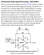
Scott Wurcer's applications info for the AD797 suggests a 2nF cap prior to the opamp I/V. I'd not say that 2nF would count as 'rather large' though as C0G goes up to 100nF comfortably.
Attachments
Scott Wurcer's applications info for the AD797 suggests a 2nF cap prior to the opamp I/V. I'd not say that 2nF would count as 'rather large' though as C0G goes up to 100nF comfortably.
Given that Scott Wurcer and the guys at ESS are old friends, and that Scott maybe not too long ago did some tests on an ESS DAC for them and found some problems for them to work on, don't know if that question ever came up.
It could be that putting a modest C0G cap there would be a good idea.
It would be great if someone would like to try it and post the findings here. I am finding myself tiring of this project though, other than what I am still curious about that is. No reason I should do all the work anyway if other people are interested too.
However, part of the reason I am tiring may be that it seems like recently not much reporting from people about making progress and being happy about improving SQ. So, maybe interest is dwindling out there. Actually, it seems like people have been curious to see what turns up here as helping with SQ, but most people seem to be looking for a more cheap and easy solution to come along. Making this board sound good while possibly interesting to read about is a lot of work, likely too much work for most readers. And I didn't get involved mainly to become a technical writer, my aim has been to help people who want a great DAC on a minimal budget. That effort has come a long way, and a fully modded board sounds quite good as things stand now.
Tell you what though, maybe I will have some more of interest to report in a few days. Have to wait and see.
I do have a cheaper solution - dunno whether its easier - so perhaps its time to open my own thread on my DAC design.... Certainly it won't suit all comers as its only 16bits.
'Work' is only tiring when it feels like work, there are no 'shoulds' here. Do it if it feels like fun, stop if not.
'Work' is only tiring when it feels like work, there are no 'shoulds' here. Do it if it feels like fun, stop if not.
Hi there. I am still interested in further improvements on this 9038q2m board. Still waiting for my schmitt triggers to reduce raise time of my new NDK clock..
The 2nF C0G cap should be tied to offset voltage (AVCC/2) though and can be soldered to the 2 input pins of opamp directly, right? Would be interesting to see if opamp temp falls with this measure. Could this also help on ESS recommended AVCC reg in parralel to the 10 uF input filter cap?
The 2nF C0G cap should be tied to offset voltage (AVCC/2) though and can be soldered to the 2 input pins of opamp directly, right? Would be interesting to see if opamp temp falls with this measure. Could this also help on ESS recommended AVCC reg in parralel to the 10 uF input filter cap?
Hello cdsgames, I have ordered this ones: SN74LVC1G14DBVR. In SPEC I cannot find anything about Phase noise..
http://www.ti.com/lit/ds/symlink/sn74lvc1g14.pdf
Based on your recommendation to put a buffer between clock and DAC and based on Markw4 proposal to do this with such schmitt Trigger I ordered this part. Raising time seems to be lower than that of NDK clock, so I thought I give it a try... If you have a better proposal (I am sure you have..;-)), pls. let me know.
The 2nF C0G cap ... can be soldered to the 2 input pins of opamp directly, right?
The cap would go across the input pins of each I/V opamp, as you say. Do you by chance have any way to measure the results? A sound card with a 24-bit A/D could probably work.
Also, I would not add a C0G cap from AVCC to ground. It could cause the AVCC voltage regulator opamp to oscillate. At the very least, one would probably want to watch what happens with the AVCC opamp with a good scope if trying something like that. Even if no oscillation one would still want to verify it did more good than harm downstream. Another reason to have something on hand to measure the audio output with.
Last edited:
- Home
- Source & Line
- Digital Line Level
- ES9038Q2M Board