I cannot see a trace where I can easily separate L & R channels from the source of AVCC cleanly. So right now I am relegated to using a common feed to both AVCC L and AVCC R. I will accept that.
I guess the question is not whether an SRC is good or not. I would tend to believe it is good. Now all of this stuff is kind of new to me. But I would think that I could accept USB on a external box, upsample as high as I can go and output to SPDIF. As opposed to getting an XMOS and then outputting to I2S.
I guess then is I am not sure what exactly the difference between an SRC and one of those XMOS or Amanero USB boards is? Do the functions cross or are they the same or does one do more than the other? I am kind of confused about this as they both accept USB but some do it in an external box and some as in an add-in card.
I'm in Canada so the proximity is not there. But hey thanks. I wish I was closer.
Regarding SPDIF, Amanero boards, etc., SPDIF is only good up to 192kHz. For people wanting to go higher and or who want DoP or DSD, it is necessary to use a different kind of interface which may be referred to as PCM or I2S, or native DSD. All those things require multiple signals operating in parallel sometimes at much higher frequencies than SPDIF will go.
Regarding upsampling, there are pretty good arguments for upsampling everything to 211kHz that would otherwise be lower, and either not support higher sample rate formats or not upsample them. It is possible to upsample with SPDIF, TOSLINK or PCM, I2S. DSD is a whole other thing, and it uses different reconstruction filtering. Upsampler hardware can work with TOSLINK, SPDIF, AES, and or PCM/I2S. The TI SRC4392 is more oriented towards SPDIF, IMHO, although it has PCM/I2S ports. The AK4137 SRC chip is more oriented towards PCM/I2S, although there are SPDIF-to-PCM and PCM-to-SPDIF chips made by ATK, it takes more chips to do some things as opposed to using SRC4392. The AK4137 also supports higher sample rates than SRC4392. OTOH, SRC4392 might be better for jitter reduction than AK4137, which is maybe a bonus feature of some SRC chips, although sometimes jitter reduction can be the primary purpose for using one. In our case we certainly don't want more jitter, but we are mostly thinking about helping to mitigate some reconstruction filter issues.
The difference between PCM and I2S has to do with the timing of the DATA signal bits relative to the LRCLK signal. There is also a BCLK signal which is the highest speed clock. PCM comes in two basic varieties, left and right justified. Right justified has to have word length specified. Shouldn't be necessary for left justified PCM or I2S.
Native DSD uses the same number of signals as PCM but they are different signals. For that reason, the same pins may be reused for PCM, I2S, and DSD.
DoP is a type of DSD that is sent using PCM signals instead of DSD signals.
Amanero boards can provide the highest speed PCM, I2S, DoP, and DSD sample rates, but they cost the most. In theory XMOS boards could do all that too, but drivers for native DSD and multi-channel sound are not free. There are free XMOS drivers for stereo SPDIF, PCM, I2S, and DoP.
Because of the very high frequencies involved, PCM signals can only run short distances. Most of the PCM signal output pins on devices cannot drive low impedance coaxial lines, so short length interconnections are necessary. It can help as I described previously to treat PCM signals like old parallel ATA disk drive signals where every other wire is a ground. That helps isolate signals from cross-talk with each other and helps to make a semi-well defined transmission line of not too low impedance for the chips to drive. Still, it helps to keep the wires short and to connect each ground wire in the cable individually at each board's ground plane. Unfortunately, the pins on most boards are not set up for such cables, so it is something you can mod if you find it necessary.
Last edited:
Thanks for the explanation.
That means that even if one were to stick to FLAC and forget DSD for the time being. SPDIF/TOSLINK would not suffice to really get the best benefits of upsampling. One would need to have a USB to I2S interface to the DAC. This would then put external USB to SPDIF or DOP as not really being able to get you there being limited to 192KHz and the only way is to then have such a USB interface essentially right on the DAC board.
Am I on the right track here?
I will pretty much always use a PC - network- NAS as the source. I have too many PCs lying around. So I am trying to understand what I will need to get it right. Right now I am using foobar on the PC. So if I want to do proper upsampling like over 192KHz, I must output via USB because Toslink and SPDIF will only allow up to 192KHz. I take it then that the driver on the PC will upsample and then send it to the Amanero Board or Xmos and then this will pass it on via I2S to DAC at at the higher upsampled rate.
Last edited:
Actually, SRC4392 could do SPDIF up to 216kHz, and the DAC should probably work with that, have to try it though. Turns out 211kHz is what people use since a 27MHz clock will get you there, although I haven't seen a low jitter one at that frequency.
Even with low jitter clocks that work up to 192kHz, that is fine for most music which is on CD, DVD, or MP3. It certainly covers the audio frequencies we can hear and a lot more, and leaves plenty of unused frequency space for reconstruction filter slow transitioning.
Remember, the reason for all the high sample rate formats is to try get better sound quality for somewhere in the frequency range we can hear. The argument from people like Benchmark and Crane Song is we can get excellent sound quality without going over 192kHz, and there is no advantage from going higher with really good data converters. In fact, some things start getting worse as sample rate goes up. For example, the lowest jitter clocks are below 50MHz, and the lower the better from that perspective.
Last edited:
Got a new Asus X470 MB with a ALC S1220 Codec. Actually it sounds better than an older external Assemblage DAC2 with the factory upgrade . Dynamics, pace, clarity. It is all over the older DAC. Never expected a built in sound chip on the MB to be superior....easily discernible. Tells me that this digital stuff have to considered as short term stuff. Keeps jumping in performance and older stuff needs to be put away. I was thinking I would take the old stuff and stick it in the office and it would be half decent. Oh Well.
Last edited:
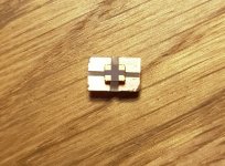
new clock on board
Hello,
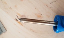
Yesterday I installed my new NDK SDA 49,152 MHz clock on my board (v.1.04). As the new clock is very tiny (2,5x2mm) I had to build an adaptor board with same size as the orig. clock. I used a 2-line print board and cut the 2 lines so that I ended up with 4 lands to solder the clock on. For soldering the clock I first put 4 stripes of copper film on the outer land parts to make the connection from the lands to the solder points on main-board on bottom side of the adaptor board. After placing this copper stripes I added some smd solder paste on each land covering the copper stripes and the lands completely. Than I placed the clock in the Center of the "cross" so that the clock contacts touched the Corners of the land fields and sticked by the solder paste. Then I heated up my new solder hot air gun on lowest Speed with around 275 °C and soldered the clock - worked perfectly. Then I installed the small board onto the main-board by soldering the copper stripes to the orig. solder points of the old clock. Before that I had to de-solder the old clock and used some modified solder iron. I removed the orig. tip and replaced it with some thick copper wire parts that I bended so that I could heat up all 4 solder Points at the same time - it worked.
How does it Sound? I would say the difference is not big and some people say the memory of sound lasts no longer than 1,5 sec. So a comparisson before / after is very difficult. Anyway I had the impression that it further cleaned up the heights (more silk like) and the stage is a little wider.
The deep bass got some more power towards kick-bass which gives a "rounder" impression with more substance and more natural feeling. As I changed the AVCC caps the same time from my "normal" 47uF aluminum to 47uF polymers 47uF (K50 with lower ESR) this might also have influed the bass performance. All in all I am very happy now with the sound allthough I already was before this clock change.
As a ranking of most efficient mods I did to my board I would judge it like this:
1) Change from voltage to current modus by i/v board -> improves dynamic and makes the sound very natural by getting rid of hiss in heights and less fatiguing , less edgy sound.
2) apply AVCC opamp PSU (inkl. own reg. for Vref) -> gives a tight and controlled bass "in-time" with the higher f-range. Pulses are very controled now and come with kick- and deep bass at same time
3) clock change and clock PSU with seperate reg. -> gives finer heights and removes some harshness. Soundstage increases a little in depth and wide.
For all using I2S Input I highly recommend some shielded wires. I installed some UF.L sockets on the bottom side to connect them. As I use SW upsampling to 96kHz incl. room correction both done by my Raspi I am not planning to apply a HW upsampler. Next step will be changing diodes of my analog PSU to HEXFREDS and care for installation into a housing such as a better heat-management. I checked temp. of my opamps and PSU transistors. opamps are around 50 °C and PSU transistors are at around 60 °C - maybe I will connect them to the housing bottom made of 3mm aluminum plate to improve cooling. Opamps get bigger cooling devices and board will be installed upside-down for better ventilation of opamps on bottom side. Output traces are cut after orig. DC Offset cap solder points and wired from there to new output connectors in the housing.
Hello,
Yesterday I installed my new NDK SDA 49,152 MHz clock on my board (v.1.04). As the new clock is very tiny (2,5x2mm) I had to build an adaptor board with same size as the orig. clock. I used a 2-line print board and cut the 2 lines so that I ended up with 4 lands to solder the clock on. For soldering the clock I first put 4 stripes of copper film on the outer land parts to make the connection from the lands to the solder points on main-board on bottom side of the adaptor board. After placing this copper stripes I added some smd solder paste on each land covering the copper stripes and the lands completely. Than I placed the clock in the Center of the "cross" so that the clock contacts touched the Corners of the land fields and sticked by the solder paste. Then I heated up my new solder hot air gun on lowest Speed with around 275 °C and soldered the clock - worked perfectly. Then I installed the small board onto the main-board by soldering the copper stripes to the orig. solder points of the old clock. Before that I had to de-solder the old clock and used some modified solder iron. I removed the orig. tip and replaced it with some thick copper wire parts that I bended so that I could heat up all 4 solder Points at the same time - it worked.
How does it Sound? I would say the difference is not big and some people say the memory of sound lasts no longer than 1,5 sec. So a comparisson before / after is very difficult. Anyway I had the impression that it further cleaned up the heights (more silk like) and the stage is a little wider.
The deep bass got some more power towards kick-bass which gives a "rounder" impression with more substance and more natural feeling. As I changed the AVCC caps the same time from my "normal" 47uF aluminum to 47uF polymers 47uF (K50 with lower ESR) this might also have influed the bass performance. All in all I am very happy now with the sound allthough I already was before this clock change.
As a ranking of most efficient mods I did to my board I would judge it like this:
1) Change from voltage to current modus by i/v board -> improves dynamic and makes the sound very natural by getting rid of hiss in heights and less fatiguing , less edgy sound.
2) apply AVCC opamp PSU (inkl. own reg. for Vref) -> gives a tight and controlled bass "in-time" with the higher f-range. Pulses are very controled now and come with kick- and deep bass at same time
3) clock change and clock PSU with seperate reg. -> gives finer heights and removes some harshness. Soundstage increases a little in depth and wide.
For all using I2S Input I highly recommend some shielded wires. I installed some UF.L sockets on the bottom side to connect them. As I use SW upsampling to 96kHz incl. room correction both done by my Raspi I am not planning to apply a HW upsampler. Next step will be changing diodes of my analog PSU to HEXFREDS and care for installation into a housing such as a better heat-management. I checked temp. of my opamps and PSU transistors. opamps are around 50 °C and PSU transistors are at around 60 °C - maybe I will connect them to the housing bottom made of 3mm aluminum plate to improve cooling. Opamps get bigger cooling devices and board will be installed upside-down for better ventilation of opamps on bottom side. Output traces are cut after orig. DC Offset cap solder points and wired from there to new output connectors in the housing.
Attachments
Last edited:
Freezebox, Thank you for the detailed update on all the mods. Sorry you did not get more improvement from the clock. In addition using NDK SDA 49,152 means some of the higher bitrate modes will not be available. But, if the clock is working properly jitter should be much lower for the modes it does work with. There have be some reports of NDK quality control on their clocks (or ones without the A suffix) to be variable. Some people will buy a few and see which ones are the best and use those, or so some of the reports on the internet seem to be saying. Maybe someone else could clarify about the history on that.
Anyway, if the clock is indeed lower jitter then you should get used to whatever improvement it offers over time. Then, you might notice more change if the old old clock was put back.
Also, hard to compare with the equivalent mod done here since the clock I used is a Crystek 575.
Sure wish we had more more build reports to get a better idea of how mods turn out on average. Your contribution for that is very useful to many others who are still thinking about what to do, so thanks again for reporting your results.
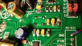
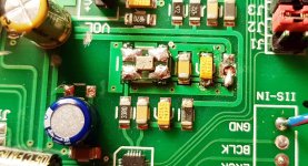
I put CCHD-950-25 on my board with dedicated LT3042 PCB.
CCHD-950-25.jpg - Google Drive
CCHD-950-25.jpg - Google Drive
Last edited:
I put CCHD-950-25 on my board with dedicated LT3042 PCB.
CCHD-950-25.jpg - Google Drive
Thank you for the pic and info. That looks like a pretty tight fit for that big clock. May I ask how did you get it in there?
Also, how do you like the sound?
EDIT: I just noticed it looks like you are using an AK4137 SRC board to drive the DAC digital audio inputs?
Last edited:
Thank you for the pic and info. That looks like a pretty tight fit for that big clock. May I ask how did you get it in there?
Also, how do you like the sound?
EDIT: I just noticed it looks like you are using an AK4137 SRC board to drive the DAC digital audio inputs?
To install this clock you just need bend some wires, solder them to the pads and then bend them to adjust to the CCHD-950 footpring.
The sound is much better than with regular clock.
Yes I use ak4137 SRC. I oversample and convert all to DSD 112. The white pcb between the boards is fifo reclock board from diyinhk in such case onboard clocks could be used for reclocking (j03 shorte, j02 opened).
Last edited:
More fully assembled ES9038Q2M box
Aliexpress.com : Buy New es9038Q2M ES9038 Q2M HIFI DAC DSD Decoder with Amanero USB audio finished from Reliable Amplifier suppliers on Mshow Store
The seller of my DAC, Mshow Audio, has a new configuration including AC sourced +/-15V power supply. The DAC board and TFT display are the same. It is not as feature rich as the one quoted by Markw4, but cheaper. The PSU is a simple 317/377 job, adequate but not LDO.The DAC has one NE5532 on socket. There are more SMD nearby which could be opamp too. Hard to tell what they are and the function. The TPA6120 headphone amp IC is a good feature for the $199 model.
I like the one I got so far. At $80 less and has more room for mod.
ES9038 ES9038Q2M DAC Decoder board Support IIS DSD DOP 384KHz with Amanero USB-in Amplifier from Consumer Electronics on Aliexpress.com | Alibaba Group
But I have to bring my own power supply and Apple remote. I should start my update mod soon.
Aliexpress.com : Buy New es9038Q2M ES9038 Q2M HIFI DAC DSD Decoder with Amanero USB audio finished from Reliable Amplifier suppliers on Mshow Store
Mark, it is nice, but al the modifications we have done on our own circuits - with inspiring eachother - makes all the units completley unique for all of us.
Some day ago one of my friends asked me; had you really achieved any development, and I could answered his question just an slightly uncertain yes.
But today I realized I have a good reference. My old Arcam 7SE CD player. At the beginning it sounded (with the internal DAC) uncomparable better than the ES9038. Today I received the SACD hybrid print of the famous Jazz at the pawnshop recording, and listen on the modified ES9038 and now it was again uncomparable, but on the other way. The ES9038 contained so much more details.....
(and even the upconversion module not yet arrived, the output amplifier can be changed to symetric, the clock could be changed, etc....)
E.g. If Mark you do not inspire working on the AVCC circuit I wouldn't do.
So guy, yes, we can buy a better ES9038 surely. But what we have done basically together, inspiring eachothers, achiving nice results on different ways, this is amazing.
So thanks to all of you...")
Some day ago one of my friends asked me; had you really achieved any development, and I could answered his question just an slightly uncertain yes.
But today I realized I have a good reference. My old Arcam 7SE CD player. At the beginning it sounded (with the internal DAC) uncomparable better than the ES9038. Today I received the SACD hybrid print of the famous Jazz at the pawnshop recording, and listen on the modified ES9038 and now it was again uncomparable, but on the other way. The ES9038 contained so much more details.....
(and even the upconversion module not yet arrived, the output amplifier can be changed to symetric, the clock could be changed, etc....)
E.g. If Mark you do not inspire working on the AVCC circuit I wouldn't do.
So guy, yes, we can buy a better ES9038 surely. But what we have done basically together, inspiring eachothers, achiving nice results on different ways, this is amazing.
So thanks to all of you...
Hello,
Yesterday I installed my new NDK SDA 49,152 MHz clock on my board (v.1.04). As the new clock is very tiny (2,5x2mm) I had to build an adaptor board with same size as the orig. clock. I used a 2-line print board and cut the 2 lines so that I ended up with 4 lands to solder the clock on. For soldering the clock I first put 4 stripes of copper film on the outer land parts to make the connection from the lands to the solder points on main-board on bottom side of the adaptor board. After placing this copper stripes I added some smd solder paste on each land covering the copper stripes and the lands completely. Than I placed the clock in the Center of the "cross" so that the clock contacts touched the Corners of the land fields and sticked by the solder paste. Then I heated up my new solder hot air gun on lowest Speed with around 275 °C and soldered the clock - worked perfectly. Then I installed the small board onto the main-board by soldering the copper stripes to the orig. solder points of the old clock. Before that I had to de-solder the old clock and used some modified solder iron. I removed the orig. tip and replaced it with some thick copper wire parts that I bended so that I could heat up all 4 solder Points at the same time - it worked.
How does it Sound? I would say the difference is not big and some people say the memory of sound lasts no longer than 1,5 sec. So a comparisson before / after is very difficult. Anyway I had the impression that it further cleaned up the heights (more silk like) and the stage is a little wider.
The deep bass got some more power towards kick-bass which gives a "rounder" impression with more substance and more natural feeling. As I changed the AVCC caps the same time from my "normal" 47uF aluminum to 47uF polymers 47uF (K50 with lower ESR) this might also have influed the bass performance. All in all I am very happy now with the sound allthough I already was before this clock change.
As a ranking of most efficient mods I did to my board I would judge it like this:
1) Change from voltage to current modus by i/v board -> improves dynamic and makes the sound very natural by getting rid of hiss in heights and less fatiguing , less edgy sound.
2) apply AVCC opamp PSU (inkl. own reg. for Vref) -> gives a tight and controlled bass "in-time" with the higher f-range. Pulses are very controled now and come with kick- and deep bass at same time
3) clock change and clock PSU with seperate reg. -> gives finer heights and removes some harshness. Soundstage increases a little in depth and wide.
For all using I2S Input I highly recommend some shielded wires. I installed some UF.L sockets on the bottom side to connect them. As I use SW upsampling to 96kHz incl. room correction both done by my Raspi I am not planning to apply a HW upsampler. Next step will be changing diodes of my analog PSU to HEXFREDS and care for installation into a housing such as a better heat-management. I checked temp. of my opamps and PSU transistors. opamps are around 50 °C and PSU transistors are at around 60 °C - maybe I will connect them to the housing bottom made of 3mm aluminum plate to improve cooling. Opamps get bigger cooling devices and board will be installed upside-down for better ventilation of opamps on bottom side. Output traces are cut after orig. DC Offset cap solder points and wired from there to new output connectors in the housing.
Hi Freezebox,
You wrote that the biggest change was the I/V re-config. I found/read your 1294 post. My question if this was the finally applied circuit? What else I have to do to have the chip in I mode instead of the V?
Can you please help me with a small summary. (I do not require that you write down everything, but if you can refer to the necessary posts - it would be also fine) what is easier for you.
Thanks,
Szabolcs
Mark, no need to excuse for anything! Not sure why the new clock did not bring a big improvement in bass - or can it be that the new KEMET polymer caps changed the bass performance into this more softer charakter? The caps are described not to be used for leakage current sensitive applications.....would tantal probably be better?
Babolcs,
the circuit in the post 1294 is what I finally use. It automatically sets the DAC into current mode. Nothing else to do to achieve that.. The left part of the circuit is on the bottom side on a seperate board while the right part was applied on the top side by modifying the existing circuit (replacing all components). What you dont see on the pictures are the vertical 6K8 resistors where the outputs of bottom board are connected to the circuit on the top side..Also be aware of the exact polarity of the opamp inputs. Pls ask if you have any further questions.
I put CCHD-950-25 on my board with dedicated LT3042 PCB.
CCHD-950-25.jpg - Google Drive
you removed the resistor at clock output on dac board - any reason / improvement doing that?
Clock should improve clarity, increase details, reduce distortion, maybe tighten imaging. Most of the very tight clean but not overly bright bass seems to come from AVCC and output stage. Bass can still be overly bright if there are remaining distortion issues. Also, good to listen carefully to cymbal tails fading into silence if you can find that on a recording. Each cymbal and drum should sound clearly different from each other. Cymbals should not sound like bursts of noise or the same as each other. Some cymbals have little rivets or chains on them to rattle. It sounds different from high hat cymbals rattling against each other. Snare drums have snare wires on the bottom head that can rattle into silence if there is a clear space in the music. You should have no trouble at all hearing how many people are singing at once and hear the details of how their voices vary as they move through singing different vowels, consonants, etc. There is potentially a great level of detail even in a CD if it is well made one, but it takes very good DAC and amp to bring it all out while keeping it sounding very natural and relaxed, and non-fatiguing.
I have been using Steely Dan's Aja album a lot since it has some clear spaces in it to hear percussion details. There some others I enjoy using for DAC evaluation, including The Best of Earth Wind and Fire, which I find to be more fatiguing unless the DAC is very good. In other words, I listen a lot to percussion and vocals for evaluation purposes. Violins and so forth are fine too, but there is perhaps nothing quite like cymbal tails for revealing a whole lot about DAC performance. Also, listening carefully to cymbals is part of the training for recording and mastering engineers. It is the first step in learning how to hear little details. Practice can help to make the skill more automatic too, if such skill is wanted. Some people definitely don't want it as they don't want to get in the habit of noticing what is wrong, because they feel it might detract from enjoying the music.
I have been using Steely Dan's Aja album a lot since it has some clear spaces in it to hear percussion details. There some others I enjoy using for DAC evaluation, including The Best of Earth Wind and Fire, which I find to be more fatiguing unless the DAC is very good. In other words, I listen a lot to percussion and vocals for evaluation purposes. Violins and so forth are fine too, but there is perhaps nothing quite like cymbal tails for revealing a whole lot about DAC performance. Also, listening carefully to cymbals is part of the training for recording and mastering engineers. It is the first step in learning how to hear little details. Practice can help to make the skill more automatic too, if such skill is wanted. Some people definitely don't want it as they don't want to get in the habit of noticing what is wrong, because they feel it might detract from enjoying the music.
Last edited:
Regarding polymer caps for AVCC, they do leak more than most other caps but that should not be a problem directly connected to the opamp output. That characteristic would tend to make them unsuitable in a high-Z circuit, or as the feedback cap in an active integrator, etc. The good thing is they have low ESR. Anyway, shouldn't hurt to try different types of caps to see if any sounds better than another, but I think there should also be a good, low-output-impedance, active regulator there too as part of the AVCC supply (unless perhaps using LiFePO4 batteries). Series resistors between regulator and AVCC pins, or caps with a lot of ESR are probably not going to be the most helpful things for DAC accuracy. Whatever caps are tried, probably good to make sure they do not adversely affect opamp stability. Standard aluminum electrolytics are likely safe from that perspective.
https://www.chemi-con.co.jp/e/catalog/pdf/Application_Note_NPCAP_090716e.pdf
https://www.chemi-con.co.jp/e/catalog/pdf/Application_Note_NPCAP_090716e.pdf
Last edited:
the circuit in the post 1294 is what I finally use.
It may help to mention what kind of resistors and caps, and tolerances.
ESS strongly recommends using thin film resistors and COG ceramic caps for the signal path. For example, I used 0.1% and 0.01% tolerance thin film 1/16th Watt Vishay SMD resistors, and COG SMD caps for the output stage signal path. In addition, bypass power pins on each opamp with a ceramic and tantalum caps direct to the ground plane using the shortest possible lead lengths. Such details are often not shown in schematics, but can be important for best results.
Mark, thank you for the cap info - very interesting file.
Regarding clock - you took the CCHD 575-50-100 clock. There is a CCHD 575x-25-100 clock available with lower ppm (25 instead of 50) and wider temp. range. Does it make a difference in Sound Performance at room-temp.? - Price is only 2 USD higher for the x - model..
Regarding clock - you took the CCHD 575-50-100 clock. There is a CCHD 575x-25-100 clock available with lower ppm (25 instead of 50) and wider temp. range. Does it make a difference in Sound Performance at room-temp.? - Price is only 2 USD higher for the x - model..
Hello,
Yesterday I installed my new NDK SDA 49,152 MHz clock on my board (v.1.04). As the new clock is very tiny (2,5x2mm) I had to build an adaptor board with same size as the orig. clock.
How does it Sound? I would say the difference is not big and some people say the memory of sound lasts no longer than 1,5 sec. So a comparisson before / after is very difficult. Anyway I had the impression that it further cleaned up the heights (more silk like) and the stage is a little wider.
.
We are using the same NDK clocks (2x) they are very good....but one thing needs to be improved. If you look at the output of the oscilators the rise/fall time is long. A good buffer with its own clean power has to be installed between the DAC ic and clocks and it improves significantly the rise/fall time (make sure the additive phase noise of buffer is insignificant ). That is important for jitter as seen by the DAC ic (research white papers on rise/fall time affecting jitter on receiving side).
- Home
- Source & Line
- Digital Line Level
- ES9038Q2M Board