I do have the SSM2141 datasheet. I am a hobbyist who like to tingle with equipment that I use. I want to understand what I am doing too. But I will have to rely on people like you to be the "competent designer". If I present a not feasible idea, you can shoot it down quick so that I will not waste time on it.Sorry, I should take a more thorough look at the datasheets for every idea that people run by. Sometimes I feel like it is better to say something rather than nothing, but without checking everything. Please though, I would like to encourage everyone to look at the datasheets carefully for parts you are considering. Not just the first page, but learn how to read the graphs and don't skip a careful read of the application notes section. I know it is a lot to do, it is for me too, but its part of being a competent designer. Over time and if you ask questions you can learn how to understand everything in a datasheet. Rarely would it require knowing any calculus or high-level physics. It is something good technicians learn how to do. If you want to design its just part of the gig, and it can get you surprising far actually.
My expertise is in hypersonic. I would be happy to answer a question of two if you have some in that area.
")
Last edited:
So is there any info on how much current AVCC requires?
Once you know this the rest follows.
T
Thank you.
My expertise is in hypersonic. I would be happy to answer a question of two if you have some in that area.
I would but I am afraid it would get too off-topic. Interesting area though.
At least you should feel very comfortable with math and science.
So is there any info on how much current AVCC requires?
Once you know this the rest follows.
T
Thank you.
FYI The 9018 has AVCC of 25mA.
....
I mentioned before there is a service manual for an older version of m-dac out there. Anybody google and look at the AVCC supply? If no, why not? You lazy?
....
lazy? no. actually I borrowed the idea about series regulator elsewhere, but m-dac uses a similar design.
Attachments
I borrowed the idea about series regulator elsewhere, but m-dac uses a similar design.
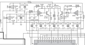
Thank you. Not just a series regulator though. Lots of distributed capacitance to assure low ESR and across a wide frequency ranges. The series regulator uses full op amp open loop gain at LF, but is frequency compensated for stability at higher frequencies.
Looks like about 2,000uf to 3,000uf total capacitance for each regulator.
A breakpoint is at the frequency where, say, the magnitude of the capacitive reactance of C405 equals the resistance of R329, or |Xc| = 10k. That gives a frequency of about 1.5kHz. Above that, one could say capacitors do an increasingly greater amount of the voltage regulation. Below that frequency the op amp is increasingly responsible for voltage regulation. (I can't see all the resistor and cap values but they appear to be the same for all the regulators, so I will just look at one example here or there.)
Gain of the op amp at higher frequencies, where Xc is much less than 10k ohms, is equal to R329/R328 = 10k/27= 370 (actually -370 because the amplifier inverts). Depending on the op amp used at some frequency its internal gain will fall off to below 370 and that gain will dominate the loop gain.
The gain at various frequencies has to be limited depending on op amp and load to keep the regulation loop stable and free of oscillations. Aside from that more gain should give better regulation. So, we want the most gain we can get while maintaining stability, or at least enough to get the DAC sound quality to the best it can be, or that we have otherwise set as a goal.
The above is a quick take on regulator loop operation by inspection. A better and more accurate model could be obtained, say, by simulation.
Besides linear stability of the regulation loop, there is also some non-linear behavior to consider. The op amp may current limit, say, when the caps are first charging up. During the transition from current limiting (which will slew up the cap voltages) to linear operation, we need to make sure the op amp will make that transition smoothly and without gain/phase and or latchup problems during the transition.
Verification that the regulator works about as expected and that the regulation it provides is adequate to maintain DAC sound quality must be measured and tested after building it.
Last edited:
thanks, Mark for the analysis. however, I am not sure whether a rather simple e-bay board deserves such a piece of engineering...
regarding the capacitance, I would think that too much will mess up the regulation, but maybe this is not the case for this circuit. indeed, for a diy-er the most important thing when building such circuits is to check the rise of the regulated output voltage when powered on, because overshoot may happen and easily burn the DAC.
regarding the capacitance, I would think that too much will mess up the regulation, but maybe this is not the case for this circuit. indeed, for a diy-er the most important thing when building such circuits is to check the rise of the regulated output voltage when powered on, because overshoot may happen and easily burn the DAC.
In the case of our simple ebay ES9038 board, which I think we should probably try to confine ourselves to here as much as practicable, it is the DAC chip itself that pretty much determines the best it can do. For this chip, the recommended ESS circuit seems to work at least up to 192kHz, as that is what mine was running at when testing at Richard Marsh's place. I don't know if it can supply AVCC current above 192kHz or for DoP and DSD. Somebody who uses those modes would need to measure. Then we can get on with this.
Right now we are spinning our wheels, so to speak. We are talking about something where we don't know what we're talking about, which is to say, we don't know what it takes to supply AVCC current above 192kHz because nobody has either (1) measured it, or (2) carefully tested DAC performance with some particular AVCC circuit at sample rates above 192kHz.
In addition, I can confirm that my DAC that was measured is running a 100MHz clock, and that the DAC board microcontroller does not program the Q2M to divide that frequency internally to reduce power consumption. Therefore, the DAC board was presumably drawing full AVCC current for 192kHz sample rate. Only thing I don't know is if turning the volume knob has any affect on AVCC current. We did have to turn the volume down a little to match the calibrated input level of the distortion analyzer.
Last edited:
....
... Right now we are spinning our wheels, so to speak. We are talking about something where we don't know what we're talking about, which is to say, we don't know what it takes to supply AVCC current above 192kHz because nobody has either (1) measured it, or (2) carefully tested DAC performance with some particular AVCC circuit at sample rates above 192kHz. ...
sorry Mark, I am getting confused indeed what we are talking about? the only point what I am trying to make is, that simple changing of LDOs to better low noise according to the datasheet in this particular implementation will not provide an improvement.
the 0dB 1kHz sinewave I measured was PCM 352kHz. of course, not the current consumed was measured, but the effect of LDO (AMS1117, LT1963, LT3045) and a series reg on THD with everything else as in original. virtually no effect changing LDOs, some -6dB drop with an op amp reg. I believe all of them can provide current enough, so why such response? from the practical point to view to improve the DAC it is irrelevant, just take what works better. still, I have a hypothesis: LDOs alone in the given implementation do not provide sufficient voltage stability due to load transient responses. So where then these load transients may come from? I guess from the high frequency switching upon code-current conversion inside the DAC. according to the info available on this forum "the output of each DAC consists of 64 MOSFET switches, and each MOSFET switch has a resistance of 50k Ohms".
so concluding, to troubleshoot this, one may need to support the LDO with a buffer opamp as you have done, or build something similar like in M-DAC ...
Sorry eziitis, I have been responding in a general way to some people who just don't want to believe that the recommended ESS circuit will work for this DAC or that who do want to believe there is some quick and easy way to do it that is even better than ESS recommends.
I think you and I are on the same page with this, but some of the readers don't seem to be. Also, what we say here isn't just a conversation between two people, we are also writing to an audience some of whom participate in posting and probably a greater number who are quietly reading along out of interest in the subject matter.
Thank you for your comments about the LDO regulators. To me it is useful information. Can't speak for others.
If we can dispense with the AVCC question then, perhaps we can move on to the IV and differential stages. In regard to that I don't think there are any ebay boards available that would be suitable choices for use with this DAC.
Like it or don't like it, the laborious truth seems to be that the full recommended ESS circuit using op amps and other components as they call out is the best way to get the full benefit of sound quality the DAC chip can provide.
Their other recommended circuits are also possibilities.
There is also the clever circuit that Victor posted. Regarding Victor's circuit, it did reduce harmonic distortion greatly according to the measurements he posted. In terms of filtering out HF noise coming out of the DAC and preventing it from getting into power amps and possibly causing trouble there, etc., I don't think it can compete with the full differential ESS circuit. Therefore, I stand by my recommendation to use the full ESS circuit.
In addition, ESS has a white paper on jitter on their downloads page: ESS Technology :: Downloads
In it they talk about relying on the DAC clock as the only one that really matters, as it is the final jitter reduction mechanism before D/A conversion. While ESS does not seem to recommend a specific clock or clock specification is it clear they think jitter an important factor in sound quality. Me too. Others, maybe haven't come to that conclusion. Yet.
So, I went ahead and used the best 100MHz clock I could reasonably find. It helped, no surprise. Maybe one reason ESS does not specify jitter is because they don't know how good it needs to be. Maybe nobody makes a clock that is good enough that no human can hear its effects, I don't know. Also, ESS doesn't advertise it but Q2M can run at lower clock speeds. It just can't do all the really high sample rate PCM, DSD, etc., with a slow clock. They do advertise that the DAC can play back all those high sample rate modes. What they are more quiet about is that one can find lower jitter clocks if one looks at lower clock frequencies, say below 50MHz. And they probably do sound audibly better for playing back CDs and DVDs which are at 44.1kHz and usually 48kHz sample rates respectively. They did not put in a mechanism to switch between two different clocks to optimize the DAC as much as possible for different sample rates. So, one has to make a choice. The banner headlines go to the high sample rates in the quest for better sound quality. That despite most recorded music probably sounding better from a DAC not optimized for those high sample rates, at least with respect to clock frequency choice.
Last edited:
@Markw4
There are probably a very great number of us who purchased this cheap board and would be interested in making improvements but lack the deep understanding of the esoteric conversations you half dozen souls are engaged in.
I'm sure if you made a separate thread titled something like "One simple modification you should make" and a simple step by step, with images, of Victors circuit implemented it would be most useful.
If you followed that up with"A second simple modification you should make" and detailed the powering of the board with separate regs that too would be useful.
Also, what we say here isn't just a conversation between two people, we are also writing to an audience some of whom participate in posting and probably a greater number who are quietly reading along out of interest in the subject matter.
There are probably a very great number of us who purchased this cheap board and would be interested in making improvements but lack the deep understanding of the esoteric conversations you half dozen souls are engaged in.
I'm sure if you made a separate thread titled something like "One simple modification you should make" and a simple step by step, with images, of Victors circuit implemented it would be most useful.
If you followed that up with"A second simple modification you should make" and detailed the powering of the board with separate regs that too would be useful.
DRONE7, Thank you posting your comments. Everyone is welcome of course.
I wish it were as simple as you seem to make it sound.
If we went in that direction there would probably be some repetition and duplication. You would have move around what you already made to fit in in the last mod for the next mod. You could have to go back and redo the power maybe a few times.
Eventually after we got through most of the mods the next one would be to go back and replace Victor's circuit with one having some HF filtering in it.
You would probably look at it at some point along the way and ask why didn't you tell us all of that before so we could save so much trouble from doing it piecemeal.
In any case, I am here as a technical guy interested in high quality audio for more people at lower cost. I already have other stuff I am working on that has priority for me like finishing up my own DAC project. Probably, once we get a few technical people to fully mod a few DACs we will start getting reports from other people besides just me about how much each mod helps. You may already know that I don't think doing one or two mods is going to cut it. It will still be a poor DAC at that point, IMHO.
If other people finish the mods and agree with me on that then we may need to look at making multi-mod-at-once board people can build, or maybe a complete start-from-scratch DAC board people can buy, maybe as just a board, maybe as a kit, maybe assembled, I don't know. Not that I want to do it myself, but maybe someone would be willing or interested in doing it. I would like to see a high quality low cost DAC available somehow.
If on the other hand, a few technical people do all the mods and can agree some mods help more than others, then we might be able to identify something like you suggest.
If it seems like all of this is taking a long time, I agree. I built one and I am not done with everything yet, as I have already described. I don't know how other people are coming along or if anybody is even trying. We aren't seeing much in way of results posted since Mike's unfortunate mishap.
In the meantime, I am willing to answer questions about how to do this or that mod that I have suggested, but I don't want to spend too much time explaining why this or that other cool idea is probably not going to work out well. Its that people can think up stuff or find stuff on ebay faster than I can give a lot of time and attention to.
For instance, if you want to pick one of the ESS recommended output stages including the very simple one, draw a picture of how you would locate the parts on a proto board or perfboard, however you are thinking of doing it, and hand draw or computer draw a schematic of how you are thinking the wires should be hooked up, then we may have a good starting point to get you some help and assistance. If you aren't up to doing that, then we just may not be at a point where we can do much to help. I'm not, let's put it that way. Maybe some of the other's here would say they are in a different situation, I don't know.
For people who can draw up a sketch and post a schematic, or who have questions at a level corresponding to that level of ability then I would encourage you to speak up and participate. Even if you don't know that much if you have a question related to the DAC or the mods, please ask. Sometimes people get some knowledge and experience and feel like they know enough to DIY without talking to anybody, without asking any questions, without discussing possible trade-offs they may be considering, etc. I would say to them that talking about it with someone else can have benefits, including if nothing else to clarify one's own thinking. Sometimes just the act of talking about something brings new insights, new ideas, better understanding,etc. It isn't a sign of weakness to talk about it and ask questions if you have any.
Last edited:
BY changing the quality of the Cset caps on the LT3042, you could hear differences in the character of the sound primarily in the lower frequencies. My final arrangement was to use paralleled film caps to correct the sound. This is something I had not expected but there is possibly more about these regs that we have not uncovered from an audio perspective.
Thanks for the info. What you are describing is completely normal, and goes for any high performance regulator. The reference filter cap is of prime important as any deviation from ideal will pass through to the output of the reg. Film caps are the best quality of course, but in larger sizes they may be prone to pick up noise. So it's a matter of finding a solution that works best for the application. You can find threads on this site where regulator designers spend a lot of time experimenting with values and types of capacitor for reference filtering.
If you are interested, here's one designer talking about optimizing an ADM7150 based regulator.
http://www.diyaudio.com/forums/vendor-s-bazaar/258789-pulsar-clock-ultra-low-noise-ocxo.html#post4057006
By the way, Twisted Pair, who have been developing ESS based DACs and peripheral parts since the ESS DACs first came on the market, currently use an ADM7150 based reg for their AVcc upgrade option.
An op-amp based solution can also work well, but there will be the exact same issue, as well as other issues. There is no particular superiority of the op-amp approach, nor any particular technical deficiency with the LT3045. Just like any high performance regulator, it needs to be optimized to give best results, and unfortunately there is no quick and easy solution.
Happy tweaking!
Last edited:
When I started my DAC project, I found this board:@Markw4
There are probably a very great number of us who purchased this cheap board and would be interested in making improvements but lack the deep understanding of the esoteric conversations you half dozen souls are engaged in.
I'm sure if you made a separate thread titled something like "One simple modification you should make" and a simple step by step, with images, of Victors circuit implemented it would be most useful.
If you followed that up with"A second simple modification you should make" and detailed the powering of the board with separate regs that too would be useful.
ES9038 Q2M DAC DSD Decoder Support IIS DSD 384KHz Coaxial Fiber DOP USA | eBay
The comment by one of the buyer, Markw_99, convinced me that this is a good basis of a ES9038Q2M box, particularly his comment about the quality of the board construction. The under $50 board price is a bonus.
I expect that the DAC I ordered should work ok as is and present many upgrade opportunity. I am still waiting for its delivery.ebayrevew said:Not the best example of what an ES9038 type DAC can sound like.
ES9038 and other Sabre DACs sound quality is very dependent on surrounding circuitry. This board would have been somewhat better with a current mode output, rather than voltage mode. However, it would have needed more than one op amp and probably cost a little more. But, maybe only $5 or $10 more. Other upgrades to power supplies and low jitter clock quality would also help, but again add up to more cost. It can be a good starting point for a do-it-yourself'er who wants a project to play around with, however.
Other than the above considerations, the board was well constructed and the seller provided helpful information. I am happy with the purchase, but have modified my board quite a bit.
Last edited:
The comment by one of the buyer, Markw_99, convinced me that this is a good basis of a ES9038Q2M box, particularly his comment about the quality of the board construction. The under $50 board price is a bonus.
If you noticed every single board by every seller that is listed under the description: "ES9038 Q2M DAC DSD Decoder Support IIS DSD 384KHz Coaxial Fiber DOP"
all of them have been given the exact same reviews by ebay! In case you don't know about it, ebay suggests to the seller what description to use. So it is actually ebay that is primarily responsible for the review being attached to so many items, some of which sell for lower cost by the way.
Whoever the buyer was it sounds like that buyer and all the other buyers found they had to modify the board to give improved sound sound quality. In fact, it looks like that buyer was the least satisfied of all the buyers who commented. I would agree with the review that my particular board was well constructed in the sense of being well soldered, parts aligned well with solder pads, clean, board is thick and sturdy enough to have some strength, holes are provided for mounting, etc. I would also agree that the particular seller I purchased from answered one question I had promptly which I thought was considerate (don't remember who it was but they were in China and didn't really speak much English), but it couldn't have been the seller in most of those ads since they are all different sellers, at least so far as I can tell.
You can thank ebay for putting the same comments with many different sellers and perhaps products. Next time you might want bear that dubious practice of ebay in mind. Also, I see that ebay didn't put any of the words in the review in bold lettering, so it seems to read a little differently sitting there with the other reviews.
Anyway, please let us know when you get the board. We are looking forward to your upgrade reports and listening impressions.
Last edited:
Thanks Spartacus, I read some of the comments of in that thread and it is squarely what I found. A certain bypass simply removed the "life" of the sound. I had yet to try the op amp reg for the AVCC when my mishap occurred.
Sure. If you notice, all the various precision regulation circuits use feedback amplifiers some of which are discrete op amps and some of which are with other circuitry bundled together as an IC. Also, it is a fact that sometimes there are things that can be done with IC amplifiers than can't be done with as well with discrete, and sometimes it can be the other way around with a discrete solution offering some advantage.
The important thing about the other thread and what is going on there is that there is a lot of trial and error, experimentation, and numerous comparisons made. Where I become concerned is when people look at specs on paper and then feel confident the design should work fine in a sensitive application without the comparison part of the process.
So long as one is willing to do all the tedious work to find the best solution i would agree with what you, Spartacus, and the other thread recommend as good circuit development practices for something as sensitive as AVCC.
However, for someone looking for a quick, easy, and good solution I would say that doing a lot of building, comparing, and adjusting different circuits might possibly end up being a little more like long and hard, rather than quick and easy. If one considers the whole process the quick and easy solution would more likely seem to be the ESS recommended one where they have already done the up-front work to find out what works best for their very high performance and very sensitive IC device. All one then has to do is build one single circuit and its done. Sounds like less work to me.
Last edited:
Agreed. and it was not further on initially that I noticed this was a mobile chip.
The other thing is that the paper was written quite a number of years ago and there are newer devices that might have appeared since including
ESS Technology :: Voltage Regulators
http://www.esstech.com/files/3414/5193/1543/ES9311_product_brief_121715.pdf
The other thing is that the paper was written quite a number of years ago and there are newer devices that might have appeared since including
ESS Technology :: Voltage Regulators
http://www.esstech.com/files/3414/5193/1543/ES9311_product_brief_121715.pdf
... there are newer devices that might have appeared since including
ESS Technology :: Voltage Regulators
http://www.esstech.com/files/3414/5193/1543/ES9311_product_brief_121715.pdf
Interesting find. I should request a data sheet. Probably have to buy $150 worth for one of the distributors to provide samples. That seems to be the minimum order for anything, $150, plus shipping & handling, tax, whatever else. Of course, probably end up with several of them in the order.
Last edited:
- Home
- Source & Line
- Digital Line Level
- ES9038Q2M Board