Tested Final Simple I/V Stage
Hi Andora
Using the schematic that xx3stksm presented earlier (Post http://www.diyaudio.com/forums/digital-line-level/314935-es9038q2m-board-18.html#post5336542) - the specific modifications that are needed to get 2V RMS and 0V DC offset at the output are
1. R7, R8, R10, R11 = 0
2. R9 = Rb (Biasing) = 1.58K
3. R12 = Rf (Feedback) = 1.58K
3. C6 = 100uf
If you can get 1.58K resistances - you will have a DC offset of 0V and 2V RMS. I.e. you will not need a coupling cap.
If you want to understand the logic behind what I did - refer to this PDF https://ocw.mit.edu/courses/media-a...g-2011/readings/MITMAS_836S11_read02_bias.pdf
Refer to the formula used for "Inverting Amplifier (DC Coupled)"
-G*Vi + (1+G)Vb = Vo
When we assume
Also note
Plugging all of them in, we get
Vi * Rf/Ri = (1 + Rf/Ri)* Vi * Rb / (Rb + Ri)
Solving, we get Rf = Rb
But I could not get exact resistances and soldering was difficult. So I bypassed the existing resistances simply didn't care to get the biasing exact resulting in me having a slight DC offset at the output. Fortunately my preamp doesn't care about it
But if you have well matched 2K resistances laying around - bypass R12 and R9 (8.3K each) with a 2K resistor to make a 1.6K equivalent. That will put you at a gain of 2.07 (1600/774)
Consider this the final analysis.
I am moving on from opamp based I/V stage at this point and going back to transformers.
As an aside - the advantages to this method of I/V are
Regards
Madds can you post last tested completed schematic for easy current stage. What is output voltage.. Any filter caps?.
Thank you D
Hi Andora
Using the schematic that xx3stksm presented earlier (Post http://www.diyaudio.com/forums/digital-line-level/314935-es9038q2m-board-18.html#post5336542) - the specific modifications that are needed to get 2V RMS and 0V DC offset at the output are
1. R7, R8, R10, R11 = 0
2. R9 = Rb (Biasing) = 1.58K
3. R12 = Rf (Feedback) = 1.58K
3. C6 = 100uf
If you can get 1.58K resistances - you will have a DC offset of 0V and 2V RMS. I.e. you will not need a coupling cap.
If you want to understand the logic behind what I did - refer to this PDF https://ocw.mit.edu/courses/media-a...g-2011/readings/MITMAS_836S11_read02_bias.pdf
Refer to the formula used for "Inverting Amplifier (DC Coupled)"
-G*Vi + (1+G)Vb = Vo
When we assume
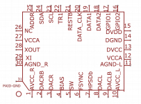
- R1 = R3 = Ri = Internal Impedance of DAC = 774 Ohm
- R2 = Rf = Feedback resistance
- R4 = Rb = Biasing Resistor
Also note
- G = Rf/Ri
- Vi = AVCC/2 = 1.65V
- Vb = Vi*Rb/(Rb + Ri)
Plugging all of them in, we get
Vi * Rf/Ri = (1 + Rf/Ri)* Vi * Rb / (Rb + Ri)
Solving, we get Rf = Rb
But I could not get exact resistances and soldering was difficult. So I bypassed the existing resistances simply didn't care to get the biasing exact resulting in me having a slight DC offset at the output. Fortunately my preamp doesn't care about it
But if you have well matched 2K resistances laying around - bypass R12 and R9 (8.3K each) with a 2K resistor to make a 1.6K equivalent. That will put you at a gain of 2.07 (1600/774)
Consider this the final analysis.
I am moving on from opamp based I/V stage at this point and going back to transformers.
As an aside - the advantages to this method of I/V are
- Single Opamp
- Existing Layout
- Simpler changes
- Better than Sabre's recommendation since there is no coupling cap at the output
Regards
Small Correction post above
R7, R8, R9, R10 = 0
And also wanted to mention that from the derivation above - one can see that Rf should be very close to Rb if not precisely equal to avoid DC offset at the output. I cannot stress this enough. If you have a DC coupled amp and you are using the digital volume control - you could blow your speakers if you do not match the resistors carefully. A DC offset of 50 mv amplified 40 times is 2V
Last edited:
I ended up picking up a HIFImeDIY DAC 2 up off eBay, it turned up today.
Haven't heard a ESS based DAC for a few months and even though this is "Only" the ES9023 I haven't put my headphones down all day. Something I love about that "Sabre" Sound, the detail on high end frequencies is something else.
This will take AC or DC, but didn't have a AC transformer, so smashed open a 6v Linear DC wall wart and desoldered the rectification circuit and voltage regulator to get me going.
Will order a talema 7v transformer this week from RS and build a case for it.
Anyway, going off track here.
Can't wait to order a ES9038Q2M board to play with now, I might end up using it to replace my Chord Qute EX, I'm really excited to have a listen.
Which board from China is the one to get, there are so many on eBay but not sure which is the "best" implementation?
Last edited:
Looks like Chord Qute EX is a rather expensive piece of kit? May I ask if you have a budget in mind for a Sabre DAC? And how much work would you be willing to do? Do you want headphone out? Have to ask because none of the Chinese DACs is very ideal, at least from my perspective. There are various options depending on how far you want to go, which maybe you already know if you have been reading the thread here.
Looks like Chord Qute EX is a rather expensive piece of kit? May I ask if you have a budget in mind for a Sabre DAC? And how much work would you be willing to do? Do you want headphone out? Have to ask because none of the Chinese DACs is very ideal, at least from my perspective. There are various options depending on how far you want to go, which maybe you already know if you have been reading the thread here.
Hi Markw4,
Something I'm not "Fussed" about with the Chord, it's good but I think its Coloured, also it's not fun like the Sabre DACs.
As much work as needed, it's all part of the fun
") I have an electronics workshop here with scopes, hot air, hakko and weller irons so not afraid to get stuck in, actually I can't wait to get my hands dirty...
I have an electronics workshop here with scopes, hot air, hakko and weller irons so not afraid to get stuck in, actually I can't wait to get my hands dirty...With that in mind I'd rather get the most basic board I can find, but not some oddity that no one else is using, so looking at the sub £40 boards on eBay.
There seems to be three types and I'm trying to work out which is the better of the 3 to start off with.
There is the Green V1.06 I see a lot of on here, this is first in my list:
ES9038 ES9038Q2M DAC Decoder board Support IIS DSD 384KHz HIFI NEW Version | eBay
Then there is a blue version which is similar, not fussed on the power input design on the PCB where you put the -15/+15 and the VR looks different.
Assembled ES9038 DAC board Q2M I2S DSD 256K Optical Coaxial Input Decoder | eBay
And then finally this "Basic" one, but has a LT1963 as well for some reason.
No filter adjustment and only I2S
Assembled ES9038Q2M board ES9038 I2S DAC PCM 192K DSD 256 HIFI ELNA caps | eBay
I will build some logic to go in this as well as I want to use a Noritake 256x64 VFD, I2S direct to a Pi and also External I2S to connect directly to a CD player and make it all remote control. That will come later as soon as i'm happy with how it sounds.
Last edited:
Can't edit, so going to reply instead.
Looking at pictures of the Green 1.06 board there is a IIC connection on the bottom of the board, so looks like this has an I2C header. If so I think I will order this one
Also no I don't need headphone out, my amp has Class A headphone amp built in already, I rarely use headphones on the HiFi, only on the PC mainly.
Last edited:
Green 1.06 seems to be the most common, and its the one I'm using. Pictures of my particular mods can be seen in photos in this post (click on the x in the lower left corner of the pictures to see full size): http://www.diyaudio.com/forums/digital-line-level/314935-es9038q2m-board-43.html#post5384519
Also, you might want to study what little public information ESS makes available, some of it is very applicable to modding Chinese DACs: ESS Technology :: Downloads
Maybe worthwhile to read through this thread starting back around where the pictures are. There are bits and pieces of possibly useful information along the way. My own effort has been to do what I can in a quest for accurate reproduction. Don't much care for approaches that try to colour the sound a little bit to make it more pleasurable to listen to. I want it to sound like I am in the mastering room when they finalize the tracks, for better or for worse. I think it should sound really good though unless perhaps the master tracks were bad the way they made them. I think the goal has basically been met (there is a Benchmark DAC-3 here for SQ comparision). What is left is mostly to package things up and finalize a few odds and ends.
EDIT: There is also some info about configuring Windows sound engine, which can cause SQ issues without warning. Most OS's now seem to do something like that for the default sound device: http://www.diyaudio.com/forums/digital-line-level/314935-es9038q2m-board-42.html#post5383552
Last edited:
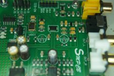
Is this the right way fore the + and - of the dac output?
Thinking of putting external I/V amplification on it.
yes, it looks correct to me.
Attachments
@democles, The picture shows the AVCC analog power supply resistor-capacitor filter for each channel (left and right) have been removed. Depending on how you want to condition the AVCC power, you might need to put those components back and solder some additional filter capacitors in parallel with the original capacitors underneath on the other side of the PCB. My own preference was to use the ESS recommended AVCC circuit and derived IV reference voltage (reference voltage = 1/2 of AVCC). Also, the side of the PCB shown may be referred to as the component-side. The other side may be referred to as the solder-side.
In addition, the DAC outputs are marked with red dots. The dots on the far left and far right are the in-phase analog outputs. The dots closer to the center indicate the inverted-phase outputs.
In addition, the DAC outputs are marked with red dots. The dots on the far left and far right are the in-phase analog outputs. The dots closer to the center indicate the inverted-phase outputs.
Last edited:
yes, it looks correct to me.
Thanks for that attachment.
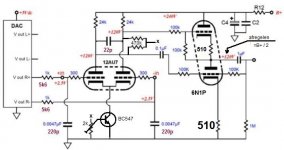
That tube schematic looks like a voltage mode circuit, not current. That's what the DAC already has, but with an opamp rather than a tube. For best sound quality you need current mode output.
Look for this thread then:
Pure Tube i/V for ES9038PRO-9028, 9018, AKM...
I will not do opamp,i wil try tube amp.
the sound then might be interesting indeed. for the low THD perhaps I/V like in
ES9038Q2M Board
or
Chinese ES9018K2M I2S DAC
would be more appropriate. however there is an opinion that the whole charm of Sabre32 lies with more or less prominent 3rd harmonic standing alone.
- Home
- Source & Line
- Digital Line Level
- ES9038Q2M Board