Hi Kay,
The (+) side of the cap goes to the node with the more positive voltage, and (-) side of cap goes to the node with the more negative voltage. Remember, voltage is always a difference between two points, not something that can exist only at one point (At least in a circuit. A charged particle sitting alone in outer space would kind of be an exception from the way we need to look at what voltage means in a circuit).
So, in the case of +-15v, the (+) lead of one cap would go to the +15v opamp pin, and the (-) lead of the cap would go to ground. For the -15v opamp pin, the (-) lead of the other cap would go to the negative opamp pin and the (+) lead of that cap would go to ground. In some cases some people may use a cap between the positive and negative power pins of the opamp and not connect the cap to ground at all. In that case the (+) lead of the cap would go the +15v pin of the opamp, and the (-) lead of the cap would go to the -15v pin of the opamp.
Hopefully, you can see how the principle in the first paragraph above works by this point. If not, please ask about anything you may be unsure of.
Last edited:
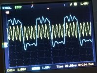
Thought I might post something of possible interest to others building DACs A couple of scope pics below show the best sounding phase relationship (that I found) between the DAC 100MHz clock (yellow trace), and the AK4137 nominally 22.5MHz clock used for all conversions to DSD. The actual frequency I am using for AK4137 in the phase-locked case is 25MHz (blue trace). Because the scope only has 100MHz bandwidth, the 100MHz clock signal should be attenuated in amplitude as it appears on the scope, since the scope frequency response is starting to fall off. Also, the ringing on the 25MHz is probably from having the scope probes grounded to the DAC board ground plane, but the 25MHz had to have been probed on the AK4137 board. So, I think the ground difference probably accounts for some or most of that ringing.
Attachments
Thought I might post something of possible interest to others building DACs A couple of scope pics below show the best sounding phase relationship (that I found) between the DAC 100MHz clock (yellow trace), and the AK4137 nominally 22.5MHz clock used for all conversions to DSD. The actual frequency I am using for AK4137 in the phase-locked case is 25MHz (blue trace). Because the scope only has 100MHz bandwidth, the 100MHz clock signal should be attenuated in amplitude as it appears on the scope, since the scope frequency response is starting to fall off. Also, the ringing on the 25MHz is probably from having the scope probes grounded to the DAC board ground plane, but the 25MHz had to have been probed on the AK4137 board. So, I think the ground difference probably accounts for some or most of that ringing.
I'm assuming you've removed the earth wire and signal input clip from CRO
probe, connected the earth sleeve with as short a lead as possible to the GP
and use only the very short probe tip for signal input.
If you haven't done above, you will be looking at a whole lot of a/ signal bounce and b/ noise from earth lead and unshielded probe.
T
Terry,
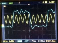
I know, but thank you for trying to inform those who may not. Actually, I have the little spring whisker ground tips for my probes. I also have one much better Tek probe that allows for more honest waveform display at around 100MHz. In this case I wanted to use matched probes to help minimize any timing skew. Unfortunately, the dac is down in a recessed area in a steel file server case, and quite hard enough for me to see where the probes are going, hold both tips in place using the more convenient clip-on grounds, and manipulate the scope controls too all at the same time. If I had an assistant to hold the probes or hold one of them it might help. I don't know if two people could look down in there without bumping heads, for one issue. In short, it was a hard measurement to make as it was. And, yes, I know how to do it the more accurate, and technically proper way. Once I noticed that I actually had saved a shot of the dac clock and the DSD clock, it turns out they are both on the same board, and and the probe grounds were clipped on a ground plane test point very nearby. In that case, I believe the ringing on the 12.5MHz DSD clock is mostly from the ribbon cable and pin header interconnects, and because it was measured at the arriving end on the dac board rather than the transmitting end at the AK4137 board. In the second, more expanded view pic, that is a stretched out view using the same capture points as in the first picture, the one that shows more waveform cycles. So, less density of sample points is visibly evident in the stretched out view and that makes it look a little more distorted than it would have appeared if taken in a separate capture at a higher sample rate.
I know, but thank you for trying to inform those who may not. Actually, I have the little spring whisker ground tips for my probes. I also have one much better Tek probe that allows for more honest waveform display at around 100MHz. In this case I wanted to use matched probes to help minimize any timing skew. Unfortunately, the dac is down in a recessed area in a steel file server case, and quite hard enough for me to see where the probes are going, hold both tips in place using the more convenient clip-on grounds, and manipulate the scope controls too all at the same time. If I had an assistant to hold the probes or hold one of them it might help. I don't know if two people could look down in there without bumping heads, for one issue. In short, it was a hard measurement to make as it was. And, yes, I know how to do it the more accurate, and technically proper way. Once I noticed that I actually had saved a shot of the dac clock and the DSD clock, it turns out they are both on the same board, and and the probe grounds were clipped on a ground plane test point very nearby. In that case, I believe the ringing on the 12.5MHz DSD clock is mostly from the ribbon cable and pin header interconnects, and because it was measured at the arriving end on the dac board rather than the transmitting end at the AK4137 board. In the second, more expanded view pic, that is a stretched out view using the same capture points as in the first picture, the one that shows more waveform cycles. So, less density of sample points is visibly evident in the stretched out view and that makes it look a little more distorted than it would have appeared if taken in a separate capture at a higher sample rate.
Last edited:
Another update on FPGAs and Vivado. Right now things are moving along kind of slowly. Have someone working on trying to take lessons learned in this thread to build a low cost commercial dac, but one a step above most of what is available out there. Don't know what will come out of it, when something might be available to listen to, etc. There is still some more work to do sort out how to possibly make a few more improvements beyond where I left my modded dac at the point I started looking into FPGA options. However, I am not doing the hardware work this time, only trying to help think things through and provide what advice I can.
On the FPGA front, Vivado is where my attention remains focused for now. There is a lot to learn about FPGA design, simulation, debugging, etc. Later will come the role of Matlab or similar for determining required numbers of taps and coefficients. Also, there are some trade offs in FIR filter topology for efficient implementation in FPGA, and other trade-offs for designing interpolation (upsampling) filters. There is also the matter of trying to implement 32-bit filters in a nominally 16-bit or 18-bit FPGA, which requires some custom work to get double-precision integer operation. And, then there is the fact that I2S/PCM serial audio serializes left and right channel audio data in one stream, so how to process data for both channels has to be decided upon. Either it would involve separating the two channels into separate streams, or processing both channels sequentially through the same filters, but swapping in and out data still in use for one channel when the other channel is being processed, and vice versa. Vivado and FPGA design are a big part of the whole undertaking as it turns out, more so than some of the other stuff. So, that is why I will be spending more time on that for awhile.
On the FPGA front, Vivado is where my attention remains focused for now. There is a lot to learn about FPGA design, simulation, debugging, etc. Later will come the role of Matlab or similar for determining required numbers of taps and coefficients. Also, there are some trade offs in FIR filter topology for efficient implementation in FPGA, and other trade-offs for designing interpolation (upsampling) filters. There is also the matter of trying to implement 32-bit filters in a nominally 16-bit or 18-bit FPGA, which requires some custom work to get double-precision integer operation. And, then there is the fact that I2S/PCM serial audio serializes left and right channel audio data in one stream, so how to process data for both channels has to be decided upon. Either it would involve separating the two channels into separate streams, or processing both channels sequentially through the same filters, but swapping in and out data still in use for one channel when the other channel is being processed, and vice versa. Vivado and FPGA design are a big part of the whole undertaking as it turns out, more so than some of the other stuff. So, that is why I will be spending more time on that for awhile.
Last edited:
Would using some more powerful hardware designed for audio alleviate the trade-offs needed?
Analog Devices just released a "reasonably" priced development module (SHARC Audio Module Evaluation Board | Analog Devices) that comes with all the development tools needed and 64-bit floating point support.
Hopefully minidsp would update their kit with the new processors and provide a ready to use module if the audio kit doesn't suit somebody's needs.
First of BRAVO to that potential project to have a DAC base encompassing all your findings, that would be great, be it Sabre... or AKM. It could be a nice modular starting base to get DIYer to the best possible level thanks to easy upgrades / mods...
On anoter note that FPGA filter bit sounds really like a big step, but perhaps not for DIYer (you are in another class Mark than the mere mortals")
That's where an available advanced product basis, perhaps leaving some doors open re soft developments while providing already a functioning basis, could be great again
Interesting, all this!
Claude
On anoter note that FPGA filter bit sounds really like a big step, but perhaps not for DIYer (you are in another class Mark than the mere mortals
That's where an available advanced product basis, perhaps leaving some doors open re soft developments while providing already a functioning basis, could be great again
Interesting, all this!
Claude
welas,
At one time I did look at Sharc and Blackfin processors. I found that they couldn't do what I need, or do what they are designed to do to my satisfaction. For example, ASRC in all of them was not of the lowest distortion available compared to standalone units. They also were limited in the types of filters they were designed to run. In particular, they did not support interpolation filters. Could be the latest, greatest one could be custom programmed to do more, but there doesn't appear to be an easy way to find out at this point. The link they have for a list of DSP types supported is only a stub, nothing is populated there yet. Mostly, devices like these seem to be aimed more at audio system integration needs. Maybe room EQ, user tone controls, maybe even electronic speaker crossovers, but not dac signal processing internals.
At one time I did look at Sharc and Blackfin processors. I found that they couldn't do what I need, or do what they are designed to do to my satisfaction. For example, ASRC in all of them was not of the lowest distortion available compared to standalone units. They also were limited in the types of filters they were designed to run. In particular, they did not support interpolation filters. Could be the latest, greatest one could be custom programmed to do more, but there doesn't appear to be an easy way to find out at this point. The link they have for a list of DSP types supported is only a stub, nothing is populated there yet. Mostly, devices like these seem to be aimed more at audio system integration needs. Maybe room EQ, user tone controls, maybe even electronic speaker crossovers, but not dac signal processing internals.
Have someone working on trying to take lessons learned in this thread to build a low cost commercial dac, but one a step above most of what is available out there.
I love this and would be interested.
In particular, they did not support interpolation filters. Could be the latest, greatest one could be custom programmed to do more, but there doesn't appear to be an easy way to find out at this point. The link they have for a list of DSP types supported is only a stub, nothing is populated there yet. Mostly, devices like these seem to be aimed more at audio system integration needs. Maybe room EQ, user tone controls, maybe even electronic speaker crossovers, but not dac signal processing internals.
Maybe I'm confused about your needs, but they have a SMID (prototype) interpolation filter here for the SHARC platform: https://ez.analog.com/cfs-file/__ke...0_interp_5F00_vec_5F00_21XI_2D00_simd.asm.zip
Maybe I'm confused about your needs, but they have a SMID (prototype) interpolation filter here for the SHARC platform...
Thank you for the link. Just downloaded and took a look at the asm file. Looks like a offline function for one channel. Doesn't look like it is set up for streaming, or for interleaving two channels. Rather it looks like something you could run on a file in a computer that would process one channel of the whole file then the other channel. What makes me think that is because FIR filter calculations for one sample depend on the samples that came before it, and maybe after it. When a filter starts it assumes what came before the first sample is all zeros. However, if one was to break a stream up into blocks for filter processing, then what came before the first sample of the second block is not actually all zeros, rather it is the samples at the end of the first block. So, samples need to saved so that the second block filter can be correctly restarted with the saved samples, not zeros. Hopefully that makes some kind of sense. Looks like they are working on going in a good direction, but the prototype software doesn't look prime time yet.
Also, the filter is a polyphase interpolation filter which is a possibility, but not something I have settled on. Then there would also be a question as to how fast it could process, say, a 256-tap filter for two channels. Could it do it for 352kHz, 32-bit stereo in real time? How about 768kHz? How about 512-taps? Don't know if there is a way to approximately estimate that.
Last edited:
Thank you for the link. Just downloaded and took a look at the asm file. Looks like a offline function for one channel. Doesn't look like it is set up for streaming, or for interleaving two channels. Rather it looks like something you could run on a file in a computer that would process one channel of the whole file then the other channel. What makes me think that is because FIR filter calculations for one sample depend on the samples that came before it, and maybe after it. When a filter starts it assumes what came before the first sample is all zeros. However, if one was to break a stream up into blocks for filter processing, then what came before the first sample of the second block is not actually all zeros, rather it is the samples at the end of the first block. So, samples need to saved so that the second block filter can be correctly restarted with the saved samples, not zeros. Hopefully that makes some kind of sense. Looks like they are working on going in a good direction, but the prototype software doesn't look prime time yet.
Also, the filter is a polyphase interpolation filter which is a possibility, but not something I have settled on. Then there would also be a question as to how fast it could process, say, a 256-tap filter for two channels. Could it do it for 352kHz, 32-bit stereo in real time? How about 768kHz? How about 512-taps? Don't know if there is a way to approximately estimate that.
You’d have to work out how you want to handle stereo, but the newer sharcs are dual-core. I believe that TAP potential could be calculated like this (newer sharcs do 2000 MMACs when utilizing SMID):
- 352khz: (2000 MMACs / 352khz) = 5,681 taps
- 768khz: (2000 MMACs / 768khz) = 2,840 taps
So you’d cut that in half for 2 channels. There also is a secondary accelerator too that can be used, but it’s slower than the main SHARC cores. ASICs are quick.
I believe that TAP potential could be calculated like this (newer sharcs do 2000 MMACs when utilizing SMID):
Well, you make an interesting case that it might work. There would be some additional overhead besides figuring out stereo, but the numbers you give might be useful as estimates of the limits of what might be done. I would have to agree that newer Sharc chips look a lot more attractive than when I last looked at them some time ago. Guess I'm interested enough at this point to take a second look at them. Appears I have some more reading to add to my to do list. Thanks again for the info.
By the way, may I ask about your interest in Sharc? Do you have some project of your own in mind?
Well, you make an interesting case that it might work. There would be some additional overhead besides figuring out stereo, but the numbers you give might be useful as estimates of the limits of what might be done.
Yes there will be some more overhead certainly depending on how you block it and things like memory access. But it’s a good rule of thumb to show that the processing power appears to be up to par.
By the way, may I ask about your interest in Sharc? Do you have some project of your own in mind?
Same exact project as you. I was considering creating a custom FIR processor via FPGA and then re-evaluated the new SHARC chips and was really surprised at just how much power those things have.
Another thing to consider is latency. Fast speed grade FPGAs can be clocked up to 500MHz or so, and some have hundreds of arithmetic slices. That means they can be massively parallel and possibly time domain multiplexed as well. For real time audio playback it would be good to be able to keep processing latency down low enough that sync with concurrent video is completely non-objectionable. If processing audio in blocks, say, then we might want to keep the blocks small enough that we only process 5ms of samples at once per channel at the most. So, overhead of buffering and processing might take up a larger percentage of time. Also, if we had to append 1,000 samples of the the previous block the beginning of the next block to prime the filter with non-zero samples, then strip them off after filtering, that would add more overhead too. On the other hand, if their interpolation filter code was modified to save the last 1,000 samples for each channel, it could be quickly primed upon initialization for the next block. It would of course be necessary to store the samples outside the scope of the filter to preserve them between filter calls, or maybe the filter could be declared static (which might save time too). Perhaps some memory could be reserved for that purpose that would stay in scope for so long as parent streaming filter process is running (if the filter were not static in memory). Depends on details of how Sharc software system works, which I don't know yet. There would also need to be way to mark blocks as continuations or new starts primed with zeros. So, more development of the prototype filter would probably be helpful. Either that, or just write a new filter. Lot's of things to think about no matter which hardware would be used.
Last edited:
Same exact project as you.
You mean I don't have to do this, you are going to do it for me?
You mean I don't have to do this, you are going to do it for me?
Hah I'm still at the "Is this a dumb thing to attempt?" phase.
Your prior post repeats a few of the same things that I also considered. One of the big pluses about the newer chips is that they have DDR3 controllers onboard. Throwing a 2GB DDR3 memory chip on the board will give you TONS of buffer room and not be that expensive. Whether this makes sense over a FPGA depends on how much delay you'd be willing to accept. For me, I'm not doing something like a recording studio application where very low latency is key, so it'd be plenty fast for me.
- Home
- Source & Line
- Digital Line Level
- ES9038Q2M Board