IVX, we can't discuss register level programming here in the forum since it would violate the ESS NDA. If you have have signed an NDA with ESS to get legal data sheets, then people who are NDA compliant can privately discuss specific design details. Also, there are no application notes available to anyone. The new style of data sheets that the industry seems to be adopting are very sparse data sheets with only the minimum necessary information. From there it is up to the designer to know how to use it. It's not just ESS either, its more of an industry-wide trend (although there may be exceptions here and there). It may require studying data sheets very carefully to understand all the information that is available.
haha, it is working now, finally, I found I mixed up pdf's 'b' vs 'd' i.e. Binary vs Decimal value )) 1 more 'score' for that blind dataseet 
PS: the only problem is different output DC voltages, it makes output opamps saturated at 5v and 0v. But at the DAC's outputs, I see the AC wave i.e. music. Hmm..
PS: the only problem is different output DC voltages, it makes output opamps saturated at 5v and 0v. But at the DAC's outputs, I see the AC wave i.e. music. Hmm..
Last edited:
With 3.3v AVCC, the average dac output voltage should be +1.65v, half of AVCC. If the offset is more, the chip may be damaged. So long as that is okay, then the issue with clipping in a voltage output stage is basically one of gain. To prevent intersample over distortion, its good to run the dac at a volume level no higher than -4dBFS, or so. That can be done in Windows or with the dac chip's internal volume control capability. If you turn it down a few dB, it may solve your clipping problem without changing gain of the output stage, and avoid some distortion at the same time.
Last edited:
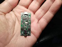
Just got my board to test. Its the blue 1. Took all the 47u caps off and exchanged them them with Rubycon 470uF ZLH caps. Then I took the 4.7 ohm resistors from the AVCC lines and made shortcuts there. The 12V input is now doing a + and - 9v for the output opamp(replaced it with a LME49720) by adding a Recom 78R9 regulator in negative output mode. Amp is now DC coupled...no caps in the output(or anywhere in the signal path). I really like the sound of this board. Sounds better then my Twisted Pair DAC or other DACs used.
Last edited:
seems output impedance of DAC is quite high.
Output impedance of ES9038Q2M should be around 820 ohms, but offset by AVCC/2. Don't know how you are using the opamp, but it normally takes more than one to remove the offset voltage from the output.
Are you running gain in the opamp that is amplifying the AVCC/2 DC offset voltage?
Last edited:
Yes, Mark, it was DC coupled, now is AC coupled, and I was able to make some measurements. THD is bad(.005%@ hifiman he400i planars load, mid of the volume slider, my goal is 10x better), and I guess I see the reason. S/N I believe the best of possible to get with AD8397 and 1.2K FB resistor <-120db(A) but need to go somewhere to remeasure with AP.
PS: SPDIF decoding isn't stable, no idea what I should tweak.
PS: SPDIF decoding isn't stable, no idea what I should tweak.
Attachments
Last edited:
If you are using voltage mode output the best you can do is about -70dB THD. You need a good three opamp I/V and differential summing output stage to get down to -120dB distortion and you would have to use the harmonic distortion compensation registers too.
I wouldn't worry about S/N too much, a good output stage can also get that down to around -120dB. Some people seem to find noise more objectionable, and other people find distortion to be more objectionable. It takes quite of bit of careful work to get down to the numbers that are possible for the dac chip, but it costs too much to do it right for super budget dacs.
The best opamps are OPA1612 or maybe LME49720. If they don't sound good, then there is something wrong somewhere, often with the power supply quality, usually the PS is not low impedance enough across the audio band, and noise isn't the primary problem.
Last edited:
So true. Thanx. Taking the 4R7 resistors out helps a lot. AVCC lines like a low supply impedance(I use separate power supplies for each supply line of the DAC). Still have to measure the distortion now.Bert,
Nice to hear you are happy with the board. It seems very strange you would find it better than a TP dac, unless perhaps it is a very old one. These dacs can be improved a lot more than what you have done thus far, but that you like it is the most important thing.
2nd FPGA and FIR Filter Update
Thought I would take a moment to update progress on working with FPGAs. Main desktop computer is up and running, but with only one OS, Ubuntu linux. I have the parts I need to restore Windows boot capbility, and I want to try CentOS linux too. I figured out how to install Vivado on Ubuntu with minimal pain and frustration, although don't know how long I will remember all the details. I have started learning Vivado, although it looks like I have about 1,000 pages of manuals to study. It is a complex and somewhat legacy appearing application that is partially script and command line driven an partially GUI. It provides a number of processing and verification steps for prospective FPGA programs. It also generates machine code for target supported FPGA chips, and can load the programs into the FPGA. Since FPGAs are volatile devices, usually there is an EEPROM and or Flash memory on the FPGA board that can be configured to load the FPGA program at power up. Earlier today, I was able to go through all the steps to get a basic test program running in a DIGILANT Arty A7-100T board. I used Diligent's manuals to set up Vivado and get the first simple demo program working. For better or worse, both of the manuals I used had errors and or were obsolete even for the older 2017 version of Vivado I elected to use. The good thing about that is I learned a lot troubleshooting, researching, and fixing all the problems. Next up will be to run the other demo programs then see if I can get the I2S digital audio volume control demo working and get a good understanding of the FPGA resources the program author decided to use. It only works with 2017 version of Vivado, which is why I selected that version. I am hoping the little Pmod I2S2 accessory arrives soon: Pmod I2S2: Stereo Audio Input and Output - Digilent
Thought I would take a moment to update progress on working with FPGAs. Main desktop computer is up and running, but with only one OS, Ubuntu linux. I have the parts I need to restore Windows boot capbility, and I want to try CentOS linux too. I figured out how to install Vivado on Ubuntu with minimal pain and frustration, although don't know how long I will remember all the details. I have started learning Vivado, although it looks like I have about 1,000 pages of manuals to study. It is a complex and somewhat legacy appearing application that is partially script and command line driven an partially GUI. It provides a number of processing and verification steps for prospective FPGA programs. It also generates machine code for target supported FPGA chips, and can load the programs into the FPGA. Since FPGAs are volatile devices, usually there is an EEPROM and or Flash memory on the FPGA board that can be configured to load the FPGA program at power up. Earlier today, I was able to go through all the steps to get a basic test program running in a DIGILANT Arty A7-100T board. I used Diligent's manuals to set up Vivado and get the first simple demo program working. For better or worse, both of the manuals I used had errors and or were obsolete even for the older 2017 version of Vivado I elected to use. The good thing about that is I learned a lot troubleshooting, researching, and fixing all the problems. Next up will be to run the other demo programs then see if I can get the I2S digital audio volume control demo working and get a good understanding of the FPGA resources the program author decided to use. It only works with 2017 version of Vivado, which is why I selected that version. I am hoping the little Pmod I2S2 accessory arrives soon: Pmod I2S2: Stereo Audio Input and Output - Digilent
ok, I have a bit improved THD, and actually 3rd harmonic 'THD_comp' coefficient = +1200 working now good in the range -3db to -10db at least. See attached screenshots.
PS: coefficient format is Eight-bit ones' complement Signed number representations - Wikipedia
PS: coefficient format is Eight-bit ones' complement Signed number representations - Wikipedia
Attachments

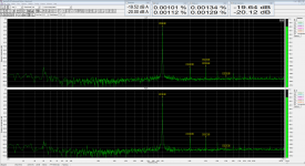
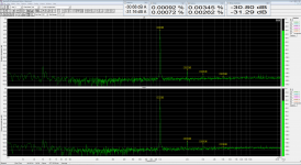
HD comp is 16-bit signed int format, which stretches across two 8-bit registers.
Interesting question about HD and phase noise (jitter). It turns out that S-D dacs can measure quite well with continuous tone distortion tests and still sound not very good. Why? I don't know all the particulars of how that can happen, but I do know there are dynamic effects with music, such as noise floor modulation, that can sound bad to some people, and not show up a all with continuous tone testing. In the case of noise floor modulation, it happens following intense musical transients that disorder the modulator state variables into a transiently excited state. As they settle down, noise is created and the noise floor temporarily goes up then back down. With steady state signals the noise floor is not modulated because the state variables are never kicked up into an excited and somewhat chaotic condition.
Regarding clocks and the effects of phase noise, a lot of what a good clock does is reduce much of the excess brightness and decrease the perception of 'weak bass' at least for Sabre dacs. Jitter significantly suppress audibility of low level reverb tails. Jitter also affects stereo separation. Instead of a relatively convincing illusion of sound coming from the middle in between two speakers, jitter makes the sound seem to come from both sides, at the speakers only. Sounds panned to different position across the width of the stereo field sound spread out as is they are multiple feet wide. With ultra low jitter, a particular sound may perceptually seem as though it is being emitted from between the speakers and with a perceived horizontal width to the sound source that may seem an inch wide or less. It may especially sound pretty convincing to a listener in the stereo sweet spot. The sounds of many things are tightened up and more in clear audible focus. The perceptual effect seems analogous to wearing lenses that are out of focus and with a bit of smeared out double vision. Removing the aberration simulation glasses brings things sharply into very clear focus, with no traces of even slight double vision. The auditory experience is similar to the visual analogy. So, to try to summarize what good clocks do is something other than change HD measurements much. But, there are multiple pleasing and enjoyable improvements to sound quality, and much improved reality of reproduction.
If you use one of the TDK NZ2016SDA clocks on its own dedicated voltage regulator, you can very low jitter performance out of a dac, and at fairly low cost. However, prices and availability are worse when purchasing in small quantities. NDK clocks with the same part number, but without the 'A' suffix aren't as good.
Last edited:
About the out-band noise of ES9038Q2M, it is really much-much-much higher than AK4490, and it goes very high, I see 50MHz, 75 and 100MHz nails + spread noise >300kHz.
Well then, I would suggest to add a LP filter at the output of the dac, and if any RF is left at the audio out RCA jacks, filter that more too. If using a 3-opamp output stage with I/V amps, some people find it helps to add about 2,000pf across the + and - outputs for each dac channel just before the I/V amps. Adding resistors to improve filtering is bad and will increase HD, so use a cap only, if there is interest in trying it. In my last dac, I twisted wires from the + and - dac outputs together and ran them along very close to the ground plane. I think that probably helped a lot without going so far as to add as discrete cap. However, I did not verify if using a small discrete caps (probably X7R SMD type) could help even more. It remains a possibility until I get around to doing some experiments to see. In the meantime, I think the lack of an external interpolation filter is the bigger issue.
To change the subject a bit, besides using HD compensation, it helps to run the DPLL bandwidth register settings for PCM and for DSD at the lowest stable settings. That improves sound quality too, although static HD measurements may not change much.
I should add that a very interesting experiment to test your power amp, speakers, and listening skills, is to adjust the HD comp registers for minimum distortion, the detune them a bit from that setting. Using some well recorded and low distortion music, try to memorize the sound with HD at a minimum, and with it detuned a little bit from minimum. Maybe change the number by 25 counts, or 50 counts, and try to see what the smallest change you can hear is. It can help to listen to cymbal tail decays in an otherwise instrumentally sparse part of a recording. Then look at an FFT and see how much the HD has changed. I think you may find that you can hear a very few dB change in HD even if the HD is down around -120dB (or perhaps more accurately with music, hear a small change in IMD). It was possible on my system here, but the AHB2 power amp is extremely low distortion, so it can be very revealing. Low volume levels and listening in the close near-field of the speaker can be very helpful for hearing very small changes is sound quality and HD.
Last edited:
")
- Home
- Source & Line
- Digital Line Level
- ES9038Q2M Board