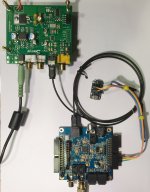
For some time I have wanted to see how far I upgrade one of the ebay Sabre DAC boards to sound as close to a Benchmark DAC-3 as possible. I'm getting pretty darn close, but I think there is a little more that can be done. More on that later, but for now a couple of photos attached below. As can be seen, output stages are fully balanced IV, power supplies are considerably cleaned up, and a low phase noise oscillator has been fitted.
very impressive!
Attached below is another photo of work on the DAC upgrade project. It shows an effort to apply one of the techniques used in Benchmark DAC-3 to improve ebay Sabre sound quality. Benchmark uses an SRC chip before the DAC chip to upsample all input to 211kHz. That allows the DAC to use a minimum phase slow roll-off reconstruction filter without producing audible transition band filter artifacts.
At this point, I have used a $30 MiniDigi SRC board that has been slightly modified to allow bootup configuration to be set via I2C bus control by a 3.3v Arduino Trinket. The SRC chip is rated for -125dB harmonic distortion. The Trinket configures the SRC to convert any input sample rate to 24/96 output. Thus the ebay Sabre DAC always receives 24/96 input. That is sufficient to allow CD and DVD audio to be played back using the Sabre minimum phase slow roll-off reconstruction filter without producing audible transition band artifacts.
Possible improvements to this setup include upgrades to the MiniDigi SRC chip and SRC oscillator to give -140dB harmonic distortion and 196kHz SRC output capabilities. Not quite up to the 211kHz pre-Sabre SRC conversion done in Benchmark DACs, but getting closer. Cost of the SRC upgrades is expected to be pretty low. SRC upgrade chips are < $15 and ultra-low phase noise clocking may not be necessary at this stage (although it should be reasonably good, similar to the original oscillator). The Sabre clock oscillator upgrade already done provides for ultra-low jitter sound reproduction quality.
As a side note, I might mention that the oscillator clock upgrade done on the ebay DAC board made a surprising-to-me amount of improvement in sound quality. Prior to the replacing the oscillator, cymbals and percussion still didn't sound close-enough-for-me to the Benchmark DAC here used for comparison purposes. The oscillator upgrade made a substantial and very satisfying difference to my ears. IMHO it is a necessity for best DAC upgrade results.
Attachments
Last edited:
It is a Crystek CCHD-575-50-100.000
http://www.crystek.com/crystal/spec-sheets/clock/CCHD-575.pdf
CCHD-575-50-100.000 Crystek Corporation | Mouser
Fitting it onto the ebay DAC PCB was a bit tight. The Crystek case is a bit larger than the original oscillator. Also, the solder pad locations are the same, but the Crystek pads are slightly larger than original. To provide a little additional clearance around the solder pads on the ebay DAC, I used a hobby knife to trim away a little of the ground trace copper around each pad. Not too much though.
Maybe this would be a good time to also mention that there is a pdf available from ESS with recommendations for op-amps, output stage circuits, and AVCC+ power supply conditioning circuits (one for the left channel and one for right). It's good reading: http://www.esstech.com/files/4514/4095/4306/Application_Note_Component_Selection_and_PCB_Layout.pdf
There is also a copy of an early evaluation board schematic which shows how to derive the output stage 'offset' voltage from the highly conditioned 3.3v AVCC+ supplies. The offset voltage should be at 50% of AVCC+. http://www.esstech.com/files/5114/4095/4310/Sabre_8_2Channel_64PIN_V3_SCH.pdf
Last edited:
Mark
First off - amazing work and your patience is admirable.
I wanted to report some findings of my own regarding upsampling and toslink
I decided to experiment with upsampling using software rather than hardware since it gave me a choice of choosing dithering algorithm and frequency. I used BitPerfect on the Mac.
I arrived at 3 conclusions on my system
1. Toslink is vastly inferior to coaxial at higher rates. The best optical cable (Lifatec is what I use now) matches coaxial until about 24/96 after which it deteriorates because of increased jitter
2. Upsampling using various dithering techniques or simply oversampling without any dithering, in my system, made the sound smooth with loss of dynamics. Both move the out of band noise further up and improve the transient response (lessen ringing) but the effect was almost like going deep into current mode on the chip. Details and imaging improved the loss of dynamics and timing.
3. Keeping the original bitrate without upsampling/oversampling with a Slow Filter yielded a good compromise.
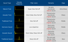
YMMV but there is something to be said about Japanese engineers describing various impulse responses and the sound. I am able to relate to it.
Here is an interesting thread that discusses the impulse response and sound
AK4490EQ Filter adjustment - Gieseler Audio - StereoNET
Cheers
First off - amazing work and your patience is admirable.
I wanted to report some findings of my own regarding upsampling and toslink
I decided to experiment with upsampling using software rather than hardware since it gave me a choice of choosing dithering algorithm and frequency. I used BitPerfect on the Mac.
I arrived at 3 conclusions on my system
1. Toslink is vastly inferior to coaxial at higher rates. The best optical cable (Lifatec is what I use now) matches coaxial until about 24/96 after which it deteriorates because of increased jitter
2. Upsampling using various dithering techniques or simply oversampling without any dithering, in my system, made the sound smooth with loss of dynamics. Both move the out of band noise further up and improve the transient response (lessen ringing) but the effect was almost like going deep into current mode on the chip. Details and imaging improved the loss of dynamics and timing.
3. Keeping the original bitrate without upsampling/oversampling with a Slow Filter yielded a good compromise.
YMMV but there is something to be said about Japanese engineers describing various impulse responses and the sound. I am able to relate to it.
Here is an interesting thread that discusses the impulse response and sound
AK4490EQ Filter adjustment - Gieseler Audio - StereoNET
Cheers
Attachments
Last edited:
Hi madds1, Interesting comments there. Thank you.
Believe optical spdif is only good to 96kHz and is not rated for higher.
For software SRC, I tried upsampling a song from a CD to 96kHz using Reaper DAW and 'Extreme High Quality' SRC mode in Reaper when rendering the output wav file. It sounded quite good to me, but Reaper's best SRC is known to be exceptionally good. Not as good as Weiss Saracon which is probably the best, but maybe a pretty close runner up.
My reason for wanting to use hardware SRC is so that it can be automatic and work anywhere.
Also working on finding a cheap USB to SPDIF interface, since USB connectivity would be a nice feature. Ordered an ebay board to try, but it won't be here for a few weeks.
It is a Crystek CCHD-575-50-100.000
Great. Thanks for the clock tip!
Hmm, looks like they just discontinued it. No wonder it was so cheap. All I can find now is some of the documentation in the legacy products section of the miniDSP website.
I guess there is no equally cheap way to do the same thing. There are TI SRC evaluation kits, but at several times the cost. An SRC evaluation kit with a better chip than the minidigi had is this one: SRC4392EVM-PDK Texas Instruments | Development Boards, Kits, Programmers | DigiKey
The SRC chip is a pretty good one and could be booted up using an Arduino or any simple microcontroller that is I2C or SPI bus capable. http://www.ti.com/lit/ds/symlink/src4392.pdf
Have to start thinking about other options I guess. It is always possible to software upsample, but it is rather inconvenient compared to using real-time hardware.
If anyone is interested, Reaper is a good DAW for upsampling and various other uses. 60-day evaluation period and non-commercial licenses are cheap. I like it. Runs on Windows and Macs, too.
Anyway, maybe if there is enough interest we could layout a PCB design for people wanting to assemble a little hardware SRC project? The parts should cost should be fairly modest.
Upgrades
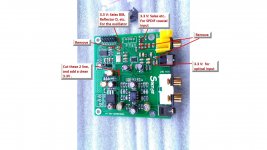
I made some upgrades to improve the sound of the board (ver 1.04). Some important steps are listed here:
1. The two power lines are cut, and a separated 3.3V is added, see picture.
2. The oscillator is powered by a separated 3.3 V Salas BIB (very low noise and among the best DIY power supply for digital). It made a high impact to the sound.
3. Also, I powered the SPDIF inlet(s) by an individual 3.3 V supply too. The original 3.3 V is shared with all the analog power(s) of the DAC chip (bad idea), yielding to the highly degraded quality of both coaxial and optical inputs. I am using mainly the coaxial, so the optical part is disabled now, but the optical input can be activated any time if needed.
4. I removed the onboard coaxial RCA, because of bad contacts both to the GND and signal.
For separated power lines, we have to remove some of the inductors (grey coloured ones), those are labeled by red circles.
Attachments
Last edited:
I have some mod experience with previous version ES9018K2M board.
And yes, 1) low phase noise clock and 2) low noise regulator are the 2 most significant mod to improve the sound quality IMO.
For more detail write up you can refer to below link for modification about:
1) capacitors
2) op amp
3) clock oscillator
4) regulator
Diy ES9018K2M I2S Dac
And yes, 1) low phase noise clock and 2) low noise regulator are the 2 most significant mod to improve the sound quality IMO.
For more detail write up you can refer to below link for modification about:
1) capacitors
2) op amp
3) clock oscillator
4) regulator
Diy ES9018K2M I2S Dac
For some time I have wanted to see how far I upgrade one of the ebay Sabre DAC boards to sound as close to a Benchmark DAC-3 as possible. I'm getting pretty darn close, but I think there is a little more that can be done. More on that later, but for now a couple of photos attached below. As can be seen, output stages are fully balanced IV, power supplies are considerably cleaned up, and a low phase noise oscillator has been fitted.
hi there..many thx for your attached images..I´ve also seen that u soldered some connectors to the I2C-pins on it..
have u something getting to work over it ? and with what ? do u use an Arduino for that ? but many thx+greets again
")
2. Upsampling using various dithering techniques or simply oversampling without any dithering, in my system, made the sound smooth with loss of dynamics. Both move the out of band noise further up and improve the transient response (lessen ringing) but the effect was almost like going deep into current mode on the chip. Details and imaging improved the loss of dynamics and timing.
Just a note, SRC doesn't improve impulse response, it has the exact same issues as normal oversampling.
Anyway, maybe if there is enough interest we could layout a PCB design for people wanting to assemble a little hardware SRC project? The parts should cost should be fairly modest.
I'd be definitely interested in a Hardware SRC project.
hi there..many thx for your attached images..I´ve also seen that u soldered some connectors to the I2C-pins on it..
have u something getting to work over it ? and with what ? do u use an Arduino for that ? but many thx+greets again
Nothing has been done with it yet. Just planning on taking a look as time permits.
I'd be definitely interested in a Hardware SRC project.
Yes, I think would probably be necessary to make an exceptionally good DAC.
To discuss a little further, it looks like to get up to 211kHz like Benchmark does it takes 2 oscillators, both of which need to be low-jitter. SRC clock would need to run at 27.000MHz and Transceiver clock at 24.576MHz, at least for something like an SRC4392. Some other odds and ends that would be needed might include SPDIF connectors and transformers, TOSLINK transmitters and receivers, etc. It can all add up depending on how much versatility one would like to have.
However, there are many ways to configure an SRC chip, and a PCB would not have to be fully populated for some or many uses. For example, if the highest sample rate was 192kHz instead of 211kHz, then only one low-jitter oscillator would be needed.
The only reason I can think of for wanting 211kHz would be to allow room for a slow roll-off filter transition band above 192kHz audio. No need for that if only using a DAC to play CDs and DVDs.
I'm a firm believer in the KISS principal, where something can be whittled down to the bare minimum for a specific use, but with optional extras that can be enabled as required. Maybe you should start a new thread for this, particularly if it will be useful for other DAC's (and I don't see why not).
I also really like your idea of configuration via an Arduino.
Last edited:
One other thing perhaps worth mentioning, an SRC chip can be programmed to attenuate the output. For the TI SRC chip in the Minidigi, output attenuation capability has a resolution of 0.5dB. That makes it easy to attenuate the digital output going to the DAC by 3.5dB, the same amount Benchmark uses to prevent intersample-over errors. It seems to be working well with the ES9038Q2M.
Great, maybe you should be using a code name for you know who, so that they don't get cranky with you cloning all of their ideas.
I submitted a request to ESS for the app notes for the 9038Q2M, thinking that it might be worthwhile look at designing a basic DAC board so that we don't have to hack up the Chinese boards so much. Unfortunately I haven't heard back from them since signing their NDA.
I submitted a request to ESS for the app notes for the 9038Q2M, thinking that it might be worthwhile look at designing a basic DAC board so that we don't have to hack up the Chinese boards so much. Unfortunately I haven't heard back from them since signing their NDA.
It sure would be nice to have more info, but if ESS gives that to you they will presumably expect you to keep it all to yourself and not share anything here.
Whatever happens on that, the hacked up Chinese DAC is working quite well, very close in sound quality to the Benchmark DAC-3 here, at least to my ears. As a point of reference here is a review including measurements of a DAC-3: Benchmark DAC3 HGC D/A preamplifier-headphone amplifier | Stereophile.com Also at Stereophile, the older DAC-2 made it to the recommended equipment list last year. Who knows, maybe DAC-3 will make it this year: Recommended Components: 2017 Edition Digital Processors | Stereophile.com
With respect to my Chinese DAC project as it stands now, I consider the DAC itself finished in terms of mods needed to get very excellent sound quality out of it. However, for anyone else interested in making one like it there may remain some issues and other considerations including: (1) a need to find another SRC and intersample-over solution (I can share the Arduino code I have for SRC4382 and SRC4392 chips), (2) a need for some kind of output buffer or headphone amp (the output op amp is loaded down too much if headphones are connected directly to the built-in stereo phone jack), (3) it would be nice to find a cheap way to get USB connectivity, and (4) I would like to find a suitable, but lower cost power supply than the Silent Switcher now in use. As time permits I am looking into some of the above items, but nothing specific to share yet.
- Home
- Source & Line
- Digital Line Level
- ES9038Q2M Board