Im assuming you mean a seperate OPA1612 than the 3 OPA1612s you used for the analogue output stage? could you explain what you mean by using it for AVCC (the 3.3V supply for the DAC chip analogue circuitry?)?Someone asked recently if OPA1612 could be used for AVCC.
It need AC 9V supply (seller say 9 to 12V is ok). So, how can I improve the power supply as the rectifiers and voltage regulators are on the board itself !Hi eljoantonyn,
Not sure what I could do to help you with that one. I don't have one like it to examine at closely or to listen to.
Of course, things like good power supplies usually help. If you buy some good ones, maybe you could keep them for use on the next dac after this one, whenever that might be.
Was there something specific you had in mind that you wanted to do with it?
I think I should check if the chips are fake or not but how is that possible ?
Is there any quick method ?
Specific..I was wondering what you think about the general layout of the board. I mean having AC to DC conversion on the DAC pcb surely is a bad idea, right ?
From reading though your contributions to this thread it really helped understand whats going on inside the Topping D50 dac, what seemed too complicated now makes more sense. it inspired some possible ways to mod it like how to configure a balanced output.
I hope you dont mind these questions, but at least it might apply to this chinese board also since they are very similar (or help other D50 owners)
On the output the Topping D50 uses filtered differential amp for a single ended output like your modded board.
I found some posts relating to a balanced output but kind of need to fill in some blanks
DC offset is ~4mV on the differential signals after IV op amps on my DAC, so that might not be much of a problem with unity gain headphone amp. Having 2 less op amps stages would be much preferable
Do you know how the resistor in series with the feedback cap affects the filtering?
Also kind of more general DAC question but do cutoff freq of DAC filters differ depending on the DAC chips ( due to oversampling rate and stuff like that)?
I hope you dont mind these questions, but at least it might apply to this chinese board also since they are very similar (or help other D50 owners)
On the output the Topping D50 uses filtered differential amp for a single ended output like your modded board.
I found some posts relating to a balanced output but kind of need to fill in some blanks
Also, just to clarify, we don't directly use a differential amp for the outputs exactly. We use opamps as transimpedance amplifiers (current to voltage converters, or I/V) as the first part of the output stage for each of the dac outputs. The next opamp after that is a differential summing amplifier/reconstruction+HF_noise filter. That is where the balanced output signals get unbalanced. After that if one wanted to rebalance the filtered outputs, an opamp single-ended to balanced converter could be used.
So the reason you would convert the signal to SE and then rebalance it is to cancel the DC offset, is that only reason?Regarding DC offsets and coupling caps. My circuit has no DC offset to speak of and has no coupling cap. That is the nature of current mode with a differential output stage. In addition, I don't have to use special value resistors to make it work. It has excellent sound quality for folks who want to try to optimize that.
DC offset is ~4mV on the differential signals after IV op amps on my DAC, so that might not be much of a problem with unity gain headphone amp. Having 2 less op amps stages would be much preferable
This is also how the D50 filters the output (circuit you are refering to without the added caps) , The D50 also has resistors in series with the I/V feedback caps like the I/V stage in this exampleMore recently I added two 33pf COG caps to each the differential amp stages. The is one cap from the non-inverting input to ground, and one from the inverting input to the output. Standard locations to roll off a differential amp.
Am i understanding you correctly that the only filtering on the balanced output of ESS recommended circuit you mention was the I/V converter feedback caps?They don't do the extra filtering for their differential analog outputs though, which makes me think it may not be essential. That being said I would probably recommend their circuit over mine with respect to the additional filtering. It's not a bad idea, I just didn't do it because I had precision 10k resistors in stock and not the other ESS recommended parts.
Do you know how the resistor in series with the feedback cap affects the filtering?
Also kind of more general DAC question but do cutoff freq of DAC filters differ depending on the DAC chips ( due to oversampling rate and stuff like that)?
laserscape,
It looks like you may have started reading from towards the beginning of the thread, where our journey kind of starts. A lot has happened between then and now. The latest schematics for AVCC and output stage circuits that we have been using, and that work quite well with ES9038Q2M, can be found in post #3003 by Mrslim: https://www.diyaudio.com/forums/digital-line-level/314935-es9038q2m-board-301.html#post5577605
In maybe the next post right after that you can see my reaction to the balanced outputs he added. I still think the most reliable way to make good balanced outputs is to use the unbalanced output stage to complete the filtering that it does, and then re-balance if desired. In probably most cases there may not be much advantage to using balanced outputs unless your power amp is located a long distance from your dac, or you are in a very electrically noisy environment. However, it is true that unbalanced signals between different parts of your system may pick up some ground-related noise that balanced lines can help avoid. One trick when using unbalanced lines is to take the unbalanced coax cable that connects, say, dac to power amp, and twist the coax out of the dac with the dac power cord down to the power strip, then continue to twist the coax with the power cable of your power amp back up to the power amp inputs and plug it in. Sometimes that may be just the fix to improve sound quality to extent power grounds are providing an alternate ground path for your signal grounds and adding some noise. Any coupling between the signals in the coax and power cables should cancel out in that case, and any power cable created ground loop will have no area to pick up noise. Neat trick.
Also, in a few posts starting with #3193: https://www.diyaudio.com/forums/digital-line-level/314935-es9038q2m-board-320.html#post5609058 I tried to summarize most of what we had done and were recommending at that point. Since then, progress has slowly continued to move ahead as we have been learning how to get the best sound quality when using AK4137 with its clock phased locked to the dac clock. Also, I think I eventually posted an output stage schematic with the balanced outputs of MrSlim removed to make it easier for output stage builders to read. I would have to look around for that, but you can probably get the idea from the earlier posts I linked to. Please let me know if any other questions come up as you continue to think about what you want to do with dac modding.
Last edited:
It need AC 9V supply (seller say 9 to 12V is ok). So, how can I improve the power supply as the rectifiers and voltage regulators are on the board itself !
I think I should check if the chips are fake or not but how is that possible ?
Is there any quick method ?
Specific..I was wondering what you think about the general layout of the board. I mean having AC to DC conversion on the DAC pcb surely is a bad idea, right ?
Hi eljoantonyn,
Looks to me like the board is pretty crowded which will make it harder to work on at all. If there is no good, continuous ground plane on the back, that would not be so good either. Any low-cost DC-DC converter like they include on that board is going cause sound quality to suffer. If you could figure out how to disable it and use an external linear power supply then the dac might start to sound better. Most likely the chips are not fake unless there are some expensive chips of a type that would be easy to fake, such as expensive opamps. In most cases the real chips are cheap and plentiful enough, or hard enough to fake, that there is not much money to be made by a counterfeiter.
Overall, I would say that if what you really want is a better dac, and you bought that one hoping it would be a good one to upgrade, you may not have ended up with the best possible choice. Sorry.
Also, maybe the most important thing we have to offer in this thread is that we have been learning a lot about how to make a rather good ES9038Q2M dac if starting out with the particular Chinese dac board we do. Probably, a lot of the details won't carry over to other dac chip architectures, and mostly only the engineering basics might be useful to apply. Even before we started in this thread, it has been known for a very long time that good power supplies, good clocks, good output stages, etc., are all needed to make a really good dac. It's pretty much everything. What that means is if you want to mod a dac it is probably better to start with one that does not have a lot of circuity already on it that you would have to figure out how to remove, or bypass, and then replace. Hopefully, that kind of makes some intuitive sense. If you want a really good dac that you mostly make yourself as you have the time and money to invest, I would still recommend trying to get one of the dac boards we use here and start on a modding journey with it. That is, of course, if it sounds like something you might enjoy doing.
Last edited:
thank you. yes, reading backwards through the pages and pages gets tiring, I was reading from the beginning... but I forget how old some of the posts are.
I see the balanced output on Mrslim's schematic uses the same filters as the Sabre example above, since the D50 has single ended output already its simple enough to try both ways, balanced output is more convenient to test it out for now.
the function of the filters is confusing to me, the aim is to cutoff ultrasonic noise and there are multiple stages to create a steeper filter but calculating CO freq on various dac LPF schematics its always well above 20kHz.
...Function of the filters is confusing to me, the aim is to cutoff ultrasonic noise and there are multiple stages to create a steeper filter but calculating CO freq on various dac LPF schematics its always well above 20kHz.
The filtering is intended to be be nominally 70kHz Gaussian LPF. Listening tests showed that the first modded dac could benefit from more filtering (something also found with early versions of Allo Katana dac, also based on ES9038Q2M). It was deemed desirable to have some 'real' poles, in part because that was what was used in to improve sound quality in listening tests with the first dac. 70kHz should be high enough that if there is any audible benefit from higher sample rates affecting lateral spacial perception, or whatever, we preserve enough of it so as not to interfere too much with any possible benefits. The chosen filter shape is likely sound good to most people since group delay effects in the audible band are pretty gentle. It's not a new approach to dac output stage filtering at all, rather it is one known to work well, maintain good sound quality, and be good enough at attenuating any HF junk so that subsequent electronics are unlikely to be adversely affected.
The balanced filtering shown by MrSlim was the same as ESS used in their early Sabre evaluation boards. The latest ES9038PRO evaluation boards use some additional opamps and filtering for balanced outputs. After forming my own views, I later found out my own preference for re-balancing the unbalanced outputs is shared by the designer of Benchmark DAC-3 (Stereophile A+ recommended, and recognized as SOA).
Last edited:
Thanks for the explanation, so it ties into hi-res audio.
I wonder if having seperate filtering stages for given sample rate (or at least a seperate filter for redbook) would be the ideal thing to have in dacs , but thats probably overkill here, maybe some high end dacs already employ something like that, like optimum filters for DSD or PCM playback.
a small factor with rebalancing route is the single 1612 used for unbalancing both channels in the D50, with dual DAC chips its a bottleneck for potential crosstalk. A new unbalancing and filter stage with OPA1611 would be ideal.
Last edited:
Yes, there is can be a small advantage using single opamps over duals, due to the cross-talk issue. However, we are still hand prototyping circuits and it is easier and lower cost to use duals, IMHO. With careful design and use of multilayer boards, I don't know that the case for singles over duals can really be justified by audible effects. For one example that I will call upon from time to time, Benchmark DAC-3 uses all duals, LME49860. If one can get a Stereophile A+ and SOA review using that, then I think any shortcoming we may have there is probably negligible.
Here at diyaudio, there tends to be a lot of focus by people in regard to things that are pretty well understood, like output stages, and insufficient focus on things that aren't very well understood, like custom external interpolation filtering. I keep saying where we probably need to focus attention at this point is not on the things we are already doing pretty well, rather we need to focus on the things we are completely ignoring. That's where we stand to pick up the most benefits.
Right now and of recent, I have been working on improving sound quality and reducing jitter by apparently not very well known means. Although use of AK4137 in upscale dac designs is not new, I don't think anyone has figured out how to fully optimize it with Sabre dacs, or even come very close to it. Not that we know of anyway. What is important to me is that the developments seem to be providing more audible benefits than any output stage tweaks probably could. Means it is probably a more useful thing to spend time on.
Last edited:
I wonder if having seperate filtering stages for given sample rate (or at least a seperate filter for redbook) would be the ideal thing to have in dacs , but thats probably overkill here, maybe some high end dacs already employ something like that, like optimum filters for DSD or PCM playback.
Not clear that there would be any advantage to different analog filters for different sample rates or for PCM vs DSD. The interpolation filters inside the dac vary of course, and they provide most of the reconstruction filtering that is needed. Also, part of what we want in our analog filtering is an absence of audible group delay effects that tend to go along with very steep Red Book sample rate (16/44) filters. We might risk doing more harm than good to sound quality when its not clear there was really a problem that needed fixing in the first place.
Also, with the recommended design of our modded dacs, anything we can upsample to 12.5MHz DSD does get upsampled since it sounds better that way. All the more so, when using low-jitter phased-locked dac and SRC clocking, along with appropriately adjusted dac DPLL bandwidth. So, we rarely playback at 16/44 anyway.
Last edited:
Found something that may be of interest to dac modders. LT makes 'Linduino One,' a little Arduino-compatible single board computer intended for controlling hardware devices over I2C and SPI bus protocols. Found out about it while looking through documentation for the LTC6954 clock divider chip. While AD does not mention Lindino support for use with LTC6954, it turns out there is a code to control the clock divider in the downloadable zip file collection of Lindino libraries and apps. Although the clock divider is controlled over SPI bus, it is probably quite possible to write a little code to make Lindino a good choice for controlling ES9038Q2M, or any of the other Sabre dac chips. Nice things about potentially using Lindino is that the price is quite reasonable, it is available from places like Mouser and Digikey, and it would not be necessary to build a shield for it in order to work with I2C and or SPI. More info: https://www.analog.com/media/en/dsp-documentation/evaluation-kit-manuals/dc2026cfe.pdf
DC2026C Evaluation Board | Analog Devices
EDIT: Probably should have mentioned I ordered one to use with the LTC6954 clock divider. When it gets it here, at some point I will look into what might be involved to use it for modded dac control too, as an alternative to the way I have been doing it with Arduino thus far. Seems likely it could be another option if it looks more attractive to some builders. Speaking of I2C control of the dac, I sort of assume that those few who have tried using I2C bus with ES9038Q2M have been using the RPi driver posted by eslei? At least, nobody has asked for any detailed information about how to use Arduino for that, something that seems a bit odd. Of course, maybe some people have already figured it out for themselves so no need to ask?
Last edited:
You can also use, what is commonly referred to in Pro Audio circles as a 'double balanced' circuit. This was, I believe, first used by a very smart Australian Pro Audio designer, the late Graeme Cohen.
For a 'double balanced' circuit, you will need total of 4 opamps. The circuit is balanced in (I-V) and that feeds a 2 opamp fully balanced OP stage. Simple and effective.
http://leonaudio.biz/double.balanced.mic.amp.notes.pdf
Integrating the LPF into this circuit can be a little tricky but I believe this is a superior way to get a balanced OP and has superior CMRR. Also it would have superior CM opamp distortion due to the fully balanced nature.
T
Thanks for the observations !Hi eljoantonyn,
Looks to me like the board is pretty crowded which will make it harder to work on at all. <snip>
There's a lot to learn for me inorder to do that. So, I'll first solve the transformer issue first. Then I'll take multiple photos of the board and try to conjure up a circuit drawing and see what can be done with the help of experts like you.
You are very welcome, of course. Happy to be of assistance.
Regarding your 'transformer issue' in the other thread, I haven't been following too closely because I don't have one of the boards to look at, and you haven't provided enough information on your own. However, it sounds like there is more than one regulator and some issue with one or more regulators getting what you think is too hot. If that is so, and if the dac is designed to be operated from one external transformer, then the one you have may be putting out enough voltage. If you can measure the DC voltage going into the regulators and the DC voltage coming out, it should be possible to figure out if you actually have a problem or not. If you do have a problem, maybe you could use two transformers, one for the low voltage regulator and another transformer where higher input voltages may be needed. To figure all that out, in addition to measuring the voltages, it would be very helpful if you could read the part numbers on the regulators. With that information, and by downloading the data sheets for the regulators it should be possible to determine if the regulators have enough input voltage from the transformer to operate properly.
Regarding your 'transformer issue' in the other thread, I haven't been following too closely because I don't have one of the boards to look at, and you haven't provided enough information on your own. However, it sounds like there is more than one regulator and some issue with one or more regulators getting what you think is too hot. If that is so, and if the dac is designed to be operated from one external transformer, then the one you have may be putting out enough voltage. If you can measure the DC voltage going into the regulators and the DC voltage coming out, it should be possible to figure out if you actually have a problem or not. If you do have a problem, maybe you could use two transformers, one for the low voltage regulator and another transformer where higher input voltages may be needed. To figure all that out, in addition to measuring the voltages, it would be very helpful if you could read the part numbers on the regulators. With that information, and by downloading the data sheets for the regulators it should be possible to determine if the regulators have enough input voltage from the transformer to operate properly.
Ok, sure !
The one getting hot is this LM7805TC https://www.engineersgarage.com/sites/default/files/7805.pdf
The one getting hot is this LM7805TC https://www.engineersgarage.com/sites/default/files/7805.pdf
 A reminder to all participants in the thread, please:
Thanks for the explanation, so it ties into hi-res audio.
I wonder if having seperate filtering stages for given sample rate (or at least a seperate filter for redbook) would be the ideal thing to have in dacs , but thats probably overkill here, maybe some high end dacs already employ something like that, like optimum filters for DSD or PCM playback.
No need for this.
ESS Sabre has inbuilt ASRC (Asynchronous Sample Rate Converter) which converts all IP sample rates to 1 output sample rate depending on what the clock freq is. This also goes for DSD.
Unless you a/ disable inbuilt digital filters and b/ run it in synchronous mode.
a small factor with rebalancing route is the single 1612 used for unbalancing both channels in the D50, with dual DAC chips its a bottleneck for potential crosstalk. A new unbalancing and filter stage with OPA1611 would be ideal.
See my post on double balanced topology. This is a superior topology for any bal in to bal out circuit if you don't want to use transformers.
T
You are right!Speaking of I2C control of the dac, I sort of assume that those few who have tried using I2C bus with ES9038Q2M have been using the RPi driver posted by eslei? At least, nobody has asked for any detailed information about how to use Arduino for that, something that seems a bit odd. Of course, maybe some people have already figured it out for themselves so no need to ask?
I use Arduino IDE with STM32 (blue pill) for ES9018K2M (9 USD board from ebay) for code testing purposes. I was inspired from the K2M code provided by HiFiDUINO many years ago and from Dimitri's blog Dimdim's Blog | DIY Audio, Arduino, Computers, Music for the hardware and software stuff (i.e. TFT code, I2C isolator schematics , etc). I presume it is not too hard to modify the code for 9038Q2M if you have the datasheet.
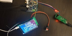
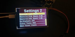
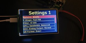
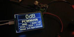
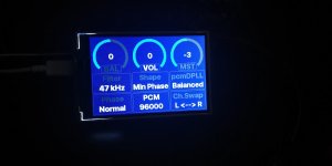
There are some pictures bellow, I am sorry for the low quality and the color aberration, but the light and my phone camera are not so good.
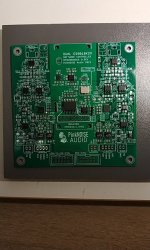
My next testing project is 8018K2M dual mono, synchronous MCLK from Si549 (I already made the Arduino library for it) so 90.xxx and 98.xxx for K2Ms, with 542 chip divider for MCLK/2 for XMOS, with simple flip-flops reclock 74AUP1G79 and galvanic isolation. I will finish the PCB's in a couple of weeks, you can see a picture below.
Attachments
ESS Sabre has inbuilt ASRC (Asynchronous Sample Rate Converter) which converts all IP sample rates to 1 output sample rate depending on what the clock freq is. This also goes for DSD.
Unless you a/ disable inbuilt digital filters and b/ run it in synchronous mode.
Uh, not sure that you have got all the details exactly right, at least respect to the newer chips, such as ES9038Q2M. However, the basic idea should be about right. I know that when Sabre dacs first came out, ESS people used to post about it here on diyaudio. At some point they decided to stop talking publicly and introduced the NDA policy. Over time they have continued to make some changes, although I don't know what they all are and couldn't speak freely about it even if I did know. Anyway, looks to me like there are more registers that could affect what the dac does with respect to output sample rate than just the a/b exceptions described above. That being said, exactly what those registers do under different conditions is not completely explained in available documentation. The way it works with ESS is if someone has signed an NDA and needs info to use a particular dac feature, ESS can provide additional information as needed to help get it working. Since most designers seem to use the dacs in basic ways recommended by ESS and as demonstrated in their evaluation boards, it doesn't seem to be too much of a burden on ESS to help the occasional designer trying to do something different. In fact, wouldn't be surprised if they may even find some bugs in some of those rare cases, since they are so rare.
- Home
- Source & Line
- Digital Line Level
- ES9038Q2M Board