Hi Guys,
The thread is now very interesting but sometimes a bit difficult to understand for a newbie like me.
Does someone can explain with simple words how to switch from voltage mode to current mode on the green 15-0-15v 9038q2m board and why current mode is better for SQ?
Thank you.
The thread is now very interesting but sometimes a bit difficult to understand for a newbie like me.
Does someone can explain with simple words how to switch from voltage mode to current mode on the green 15-0-15v 9038q2m board and why current mode is better for SQ?
Thank you.
Hi Adson,
To my understanding the 7808 takes the +15V and makes a first step voltage reduction 15V->8V to not overload and maybe have better PSRR for the 2nd step 3,3V AMS1117 reg. Also 5V should work here to feed the AMS1117 reg.
I think you could also directly feed clean 3,3V to the output of the AMS1117 after removing this one.
I would also be interested for some better alternatives for 7808 and AMS1117...
Hello and thank you for advice.
Just a five minute ago I have replaced AMS1117 by LT1763. I have soldered it (in soic8) into soic-dip adapter and have added some (required by datasheet) connectors and capacitors right to the adapter. I have left L7808 as out of the box (may be I will replace it later, may be not).
I had have no time to check the sound very well, however (to my ears) there are some differences to the better side.
So, let it be (I mean this mod).
(Sorry for my English, I'm not a native speaker)
Hi terry22,
post #73 shows a schematics for the current mode. Look the pdf measurement files for this circuit compared to orig. voltage mode and you see the improvements in THD.
thank you
thank you
hi Terry22
..i am in the same boat as you.
") . i try to follow here........ but...
. i try to follow here........ but...the pdfs are on page 6 ...post #58
chris
hi Terry22
..i am in the same boat as you.
the pdfs are on page 6 ...post #58
chris
Thank you Chris,
I really try but it is not so easy to understand the modifications needed by current mode.
Something I would like to do is write some detailed instructions with photos for upgrading one of the newer boards, the one I have is version 1.06. However, its going to take some time. Probably won't have parts here for another week. Then have to start on it. If people are interested once I have something, I would be happy to post here and answer questions. But, some patience will probably be needed.
Also, the current mode output isn't the only issue. As I previously wrote, the existing board I have can sound really bad due to aliasing noise and distortion (although a different output filter choice using the jumper settings might help in some ways, it may also hurt in some other ways), and also is very sensitive to power supply quality. Just fixing current mode leaves most of the problems.
Don't know about earlier versions of the board because I don't have one to examine carefully. However, the one I have is a double sided circuit board, so all the traces are visible. That makes it possible to sketch up a schematic and analyze the circuit.
Another thing to know is all the chips have visible writing on them with part numbers. I small flashlight and a magnifying glass make it possible to read the them. The DAC chip is the tiny rectangular IC with lots of pins. The oscillator is the small gold colored rectangular box very near the DAC chip. There are two AVCC+ pins on the DAC chip on the same side where the audio outputs are located which run over to the opamp. There are two RC filters, one for each AVCC+ pin very near the DAC. Each filter has an electrolytic capacitor, a small ceramic capacitor chip, and a resistor connecting to the +3.3 volt power line from the 3.3v regulator. Those two AVCC+ pins are very sensitive to any small imperfections in 3.3v power quality. Again, these descriptions apply best to the 1.06 version.
In addition, the current mode schematic you guys have been referring to is a balanced output version with plus and minus outputs. For best results they need to be combined using a differential amplifier circuit, or instead use a different current mode mod by Victor.
I don't have time to go into more detail for at least another week. If you can wait, or if somebody else can jump in to help, you may be in a better position to decide what you want to do.
Last edited:
Just to add, Victor's single-ended output current mode mod schematic is in his post here:
http://www.diyaudio.com/forums/digi...chinese-es9018k2m-i2s-dac-16.html#post5174874
http://www.diyaudio.com/forums/digi...chinese-es9018k2m-i2s-dac-16.html#post5174874
I'll just add to Mark's post that Jens's and Victor's I/V implementations are just examples of what one can do. In a general sense they're all "opamp-based transimpedance amplifiers", and should one do a search of that, you will find a LOT of good information from major manufacturer's application notes about how to design one.
Likewise, to be explicit: there's no "switch" to turn the ESS DACs into "current mode" versus "voltage mode", that wholly depends on what sort of load you put on the output of the DAC. In "voltage mode" the DAC is loaded with a very high impedance, thus the DAC's output will swing it's entire available voltage range while delivering very little current (proportional to the digital input stream, of course). This is how the boards are presently configured, where the opamp is configured as a noninverting buffer.
In "current mode" the load impedance is extremely low, thus the DAC's will deliver a current that is proportional to the input, e.g. the maximum digital input may correspond to +10 mA, and the maximum negative to -10 mA (numbers out of a hat).
There's a transition region at some load impedance that will not behave as either a "clean" voltage source nor a clean current source. It's going to be when the input impedance is roughly equivalent to the output impedance of the DAC (used to be around 750 or so ohms on older models?). Best practices for the ESS DACs is to load their output and run them in "current mode".
I tried to use as clear of language as possible, so that anyone confused by the terms should be able to get some good hits on your web search of choice. But go ahead and ask.
Just to add, Victor's single-ended output current mode mod schematic is in his post here:
http://www.diyaudio.com/forums/digi...chinese-es9018k2m-i2s-dac-16.html#post5174874
Do you plan on implemeting this yourself? Would you mind snapping some High res pictures of what it looks like when you're done? I'd like to see if this is worth pursuing (Buying a new board + modding it as described) compared to just waiting for something that's better implemented.
Does anyone have any links to otehr DAC's that are better implementations of the 9038q2m without really big prices? Currently, I'm looking at the Pro Ject Pre Box S2 Digital or the Pro Ject Pre Box S+. Former is a dual-mono config, while the latter is a single chip.
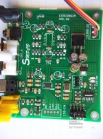
Attached is a photo of the 1.06 PCB with Electrolytics and Op-Amp socket removed. Two of the electrolytics were the +-15 volt rail filters, so something needs to go back there. Also near the op-amp socket are the two output coupling electrolytic holes.
At the other end of the PCB it can be seen where AVCC+ electrolytics have been removed, and a few components and signals have been labeled.
At the other end of the PCB it can be seen where AVCC+ electrolytics have been removed, and a few components and signals have been labeled.
Attachments
Attached is a photo of the 1.06 PCB with Electrolytics and Op-Amp socket removed. Two of the electrolytics were the +-15 volt rail filters, so something needs to go back there. Also near the op-amp socket are the two output coupling electrolytic holes.
At the other end of the PCB it can be seen where AVCC+ electrolytics have been removed, and a few components and signals have been labeled.
So this is where you'll be plugging in the modded circuit described in the post?
So this is where you'll be plugging in the modded circuit described in the post?
Probably on the solder side of the PCB. It is mostly barren ground plane. Probably mount some little SMT proto-boards there. The op-amps only have 8-pins, and the proto-boards are for 16-pins or more. Using all SMT parts, hopefully they can be mounted on the extra pads, and double up on some of the op-amp pads. That and a few tiny interconnecting wires should do it. Wires can also come up to the top through vacated through holes, or I can drill a few new ones. It's only double sided so no hidden layers to hit. It shouldn't be too hard, I tested out the concept a little on some scrap.
Probably on the solder side of the PCB. It is mostly barren ground plane. Probably mount some little SMT proto-boards there. The op-amps only have 8-pins, and the proto-boards are for 16-pins or more. Using all SMT parts, hopefully they can be mounted on the extra pads, and double up on some of the op-amp pads. That and a few tiny interconnecting wires should do it. Wires can also come up to the top through vacated through holes, or I can drill a few new ones. It's only double sided so no hidden layers to hit. It shouldn't be too hard, I tested out the concept a little on some scrap.
Awesome sounds good - any change you have measuring equipment to respond with some confirmation on the numbers that were reported on the original mod post?
@Markw4....Thanks for your kind offer to write up the mods you're making ...I'm sure I and many others will be most interested in trying them.
I do not believe there is much difference between our V1.04 and your V1.06 boards but that will be more apparent once we see the mods you make.
(I think the difference is having an extra onboard plug for single 15v powering and a 5v out on the i2s line on the V1.06.... V1.04 has neither. So the changes may be just for OEM options rather than any performance )
Last edited:
Awesome sounds good - any change you have measuring equipment to respond with some confirmation on the numbers that were reported on the original mod post?
I'm working on a notch filter. Right now I can look at the spectrum of single or double tones, but not at really low levels. 2nd and 3rd harmonics are currently right around where others have shown them while still using voltage mode output stages.
The effects of power supply quality on sound when I call it done might or might not be visible depending on what the actual level is.
Things like left to right stereo imaging and jitter, if I decide to do something with the clock, aren't really measurable here, but I do have a Benchmark DAC-3 available for A/B listening comparison. We'll see.
I might be able to send it off to someone else eventually, if anybody is set up to test it and feels like doing it.
Last edited:
I'm working on a notch filter. Right now I can look at the spectrum or single or double tones, but not at really low levels. 2nd and 3rd harmonics are currently right around where others have shown them while still using voltage mode output stages.
The effects of power supply quality on sound when I call it done might or might not be visible depending on what the actual level is.
Things like left to right stereo imaging and jitter, if I decide to do something with the clock, aren't really measurable here, but I do have a Benchmark DAC-3 available for A/B comparison. We'll see.
I might be able to send it off to someone else eventually, if anybody is set up to test it and feels like doing it.
How about something like a frequency response graph?
I do not believe there is much difference between our V1.04 and your V1.06 boards but that will be more apparent once we see the mods you make.
Could be its apparent already if you look at the picture I posted earlier today. You can see all the traces on the PCB and read many of the parts values if you blow it up to full size. Don't know how it looks compared to previous revs.
How about something like a frequency response graph?
It's flat. Or, do you mean for the reconstruction filters? The passband ripple (depending on filter type) is tiny to look at, although it and phase might be audible. They probably are to some people. If that's what you're interested in, the built-in ES9038 DAC filters are digital and have already been documented and graphed elsewhere.
Do you plan on implemeting this yourself? Would you mind snapping some High res pictures of what it looks like when you're done? I'd like to see if this is worth pursuing (Buying a new board + modding it as described) compared to just waiting for something that's better implemented.
Does anyone have any links to otehr DAC's that are better implementations of the 9038q2m without really big prices? Currently, I'm looking at the Pro Ject Pre Box S2 Digital or the Pro Ject Pre Box S+. Former is a dual-mono config, while the latter is a single chip.
Indeed, such modding is relatively simple task. Yesterday I have implemented and checked Victor's circuit on through hole proto PCB from the scratch for one channel less than 2 hours.
Also, as I mentioned before, I have replaced AMS1117 by LT1763 due to its better noise parameters.
Definitely, SQ became much better. Version on PCB is 1.04.
I plan to implement the second channel, then to place proto PCB as "second floor" over original PCB and finally connect the outs of this PCB to original connectors.
Unfortunately, I have no access to my equipment untill Monday and I can not take a photos, but (let me repeat myself) such mod is a really simple task and, in my opinion, it must have.
You just need a) to solder I/V circuit, b) remove four resistors from original PCB (DAC1, DAC1B, DAC2, DAC2B), c) connect inputs of your new patch PCB to their pads (and, sure, connect power and 3.3V), d) cut off PCB traces near the outputs and e) solder the outputs to these traces.
Also as the alternative I'm thinking about fully simmetrical I/V stage followed by summator. In this case it is possible to implement some kinds of headphone's output using, for example, TPA6120A.
Finally I was looking too for the cheap board with ES9038q2m with current mode implemented out of the box, however, I can not find it. There is at least one Chinese PCB with ES9028q2m with current mode, however, it has no Opt and Coax inputs, nor MCU for volume and filters and so on, so I have decided to leave ES9038q2m PCB with mods.
- Home
- Source & Line
- Digital Line Level
- ES9038Q2M Board