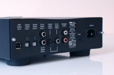
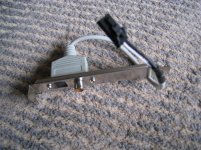
Need help. Digital coaxial input of my Rega DAC is not working anymore. Other inputs such as optical input and USB input work OK. I think it happened because I connected SPDIF bracket to SPDIF connector in wrong direction by mistake. I am currently using the optical input but want to fix it if I can. I can do lead welding (basic level) but don’t know what part is causing this problem. Could anyone tell me what is wrong?
Attachments
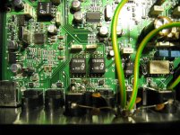
I've just checked continuity of the pulse transformers. Front legs of those two in front of coaxial input showed no connection while legs (1 and 4) at the back are connected. It seems they are damaged somehow. Anyone knows where can I buy these pulse transformers - 77TB-291DCNL? I could not find them anywhere.
I doubt it would be the Transformer.
Its Impedance will be 75 to 100 Ohms but its DC Resistance will almost certainly be a lot lower. Your reading of '0' will be OK.
The Transformers have 8 Pins, physically the will only have four connections though, two for the Primary, two for the Secondary.
The other four Pins will be unused and just for stability.
Note. Some higher quality Transformers may have more connections, such as a 'Screen' connection maybe.
I doubt the REGA Transformers will have though.
I would really consider accepting the previous poster's wisdom and seriously take a good look at the RCA Socket connections to the PCB, your fault will almost certainly lie here.
Measure from the RCA Outer to one of the Pins on the Transformer, one of them should be a direct connection to the Outer of the RCA andf you should get a '0' reading.
Then measure between the Inner of the RCA Socket to one of the other Pins of the TX, again, one of the TX Pins should measure 0 OHMS DC Resistance to the Inner of the RCA.
If they don't, there's your problem.
If they do, then yes, your fault lies elsewhere. It could be the TX but I seriously doubt it. What ''wrong voltage'' did you apply? If you put Mains up it then yes, the TX will be damaged.
If you just connected the Digital Signal the 'wrong way around' (positive to negative/negative to positive) then you will not have damaged anything. It will still work that way around. The Digital Signal would just be 180 degrees out of phase. Some DACs have a switch to do just that.
Do you have an oscilloscope? Some more accurate measuring of the Signal route would be helpful.
P.
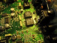
I can't see any bracket in the pictures, but if you applied 5 or 12V directly to the pulse transformers without some sort of current limiting, they can be toast. There can also be a short on the lines that go from the RCA to the Pulse transformers or inside the RCA jack and that gives You a 0V reading. By the way the soldering of the ??? under the first (left) transformer on the picture looks suspicious. Clean that flux and inspect.
It looks to me as though there is no Resistor in series with the signal to the Left TX.
There is a 75 OHM Resistor in series with the O/P from Pin 8.
I have used a Yellow Line to indicate my thoughts on the route the signal takes to Pins 1 & 4 (I/P'S) to the Left TX.
The Dotted Yellow Lines are my guess as to how the signal is routed (underneath) to the Right TX. I presume this is Coax In 2 ? Do both not work?
It looks to me like Pins 5 & 8 are the O/P's, Pin 5 looks like it's 0 Volts.
The other components which can be seen attached to both Pins 5 of the TX's will be some Caps between Digital 0V and Main Circuit 0V.
Cheers,
P.
P.S. The Soldering on the RCA Socket looks very poor to me.
Attachments
Last edited:
Hi all, Thanks a lot for the comments. I really appreciate.
Yes. Both coaxial inputs don't work.
I maybe wrong but the reason why I think the transformers are damaged is that they showed no connection between the 1 and 4 pins on the input side - both of them. I think pin 1 and 4 should show connection if it is not damaged.
When I connected the bracket in wrong direction, I think wrong voltage has been applied because on the connector pins on my computer PCB are 1. Ground, 2. SPDIF, 3. VCC. It should have been connected to 1 and 2 but I knew it was connected to 2 and 3 by an error.
The other news is that the transformer manufacturer YDS replied to my email and advised me that they could supplied the transformers to me - I still don't know how much it will cost yet though.
Thanks to Extreme Boky for your suggestion about the substitute transformers. It was a really fresh idea. I will certainly consider the parts if there is any problem with obtaining the original parts.
Anyway, I will check the RCA again and also the resistance (resistors) tomorrow to make sure.
Thanks again and I will post all the progress as soon as it happens
Hi all, Sorry. I should have said “SPDIF output motherboard bracket. I was using only 2 pins for coaxial.
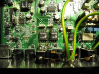
I’ve just checked continuity between the RCA and the transformers and it showed, despite poor soldering, the RCA and 1 and 4 pins of the transformers are connected. However, those 1 and 4 pins are not connected each other.
I also checked the pulse transformers linked to USB and found its 1 and 4 pins are connected. Thanks.
Attachments
Are You sure the bracket is still working ? I mean computer connected to an amp or digital recorder via coax.
If there is no reading between pin 1 & 4 the transformer is surely toast.
You could try some few windings 10-20 on a small toroid put a RCA on the primary side and try the secondary between pins 5 & 8 on the board... to see if you can get any signal in.
Or .. leave the toroid out and connect a small limiting resistor say 100 ohm in series directly with pin 8
Last edited:
Hi all, Finally I have received the parts from Synergy Audio Visual (Australia Melbourne) and replaced the faulty pulse transformers. Although my soldering was not pretty, I now can use the coaxial input again. Thank you all for the advice – because I didn’t have any idea where to start at the beginning. By the way, the Chinese pulse transformer manufacturer has not replied to me since I told them I only need two (2) of them. I think they didn’t like the small quantity order. Fortunately Synergy Audio Visual (Rega distributor) ordered the parts for me at the cost of $40 ($15 x 2 plus $10 postage). They are different brand but cannot see any difference other than the brand.
Attachments
- Status
- This old topic is closed. If you want to reopen this topic, contact a moderator using the "Report Post" button.
- Home
- Source & Line
- Digital Line Level
- Rega DAC SPDIF DIgital coaxial input not working