I have some goodies coming in the mail soon...
Raspberry Pi 3 Model B
iFi iPower 5V
Allo Kali
Nice! I have all my spare/extra RPI HAT boards built up and debugged now. I'm giving them all at least 24 hours of constant run-in just to inspire some confidence in my assembly skills. Another week or so and I should be able to officially start the mini group buy.
...have you tried his lingDAC droop correction filter with your creation? I can see that this filter would be much more time-consuming to accurately implement, but I am nonetheless curious about if/how I could retrofit it on your board down the road...if I ever get a nicer multimeter that can measure inductance...
I have not. The "scope" of this thread/project has grown; if you read the beginning of the thread, it was originally about the 8x "front end". That board was intended to be either a super-simple passive I/V DAC, and/or a "tinkerer's delight", in that you could easily experiment with more/less tda1387 chips, balanced/single-ended, different I/V schemes, filtering, buffers, etc. So that board would be the ideal candidate for all the additional "downstream" goodies that Richard has developed.
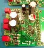
Then I got sidetracked with the RPi HAT stuff. Those (both the single-ended one pictured above, and the in-progress balanced-out version) are intended to be "80-20 DACs". Meaning, 80% of the benefit, at 20% of the cost/effort (emphasis on fun, easy, cheap; imperfect sonics, but still enjoyable). That said, while I haven't thought much about piling on filters and fancier I/V stages, I think it's simple enough that it shouldn't be too hard to add those features.
I may send out built up filter boards in exchange for listening reports")
I'm not sure which is more incredible-- 1) The chance that I could get to be one of the first to hear your circuit...
or
2) The fact that you have a girlfriend who helps with your DIYA pursuits!
My wife just makes fun of me and jokes about "flux capacitors" (à la Back to the Future) every time I broach the subject...
I wonder if there is any way I could rig up a toggle switch to facilitate rapid A/B comparison of the two filters.
I think Matt's been waiting on availability of a PCB - happy to report that my gf's PCBs have now arrived and I'm into building up the first one. Once I'm sure its fine the manufacturing data will be available on request.
I'm also interested in getting some listening feedback from people in a position to make comparisons to other DACs, particularly multibit ones. In such cases I may send out built up filter boards in exchange for listening reports
Looking forward to hopefully trying one out
Since I assume the DAC's RCA jack locations are not identical to any commercial product, I'll probably just go for a simple "dog bone" style acrylic top and bottom with standoffs in between. I guess that leaves it susceptible to dust, though.
My stuff usually has caps and stuff added/hanging off, so I like to hide it in boxes when I can
@stellarelephant, @randytsuch, @luxury54 :
Are you guys interested in giving me some listening feedback if I send you each a built up filter board? Before I spend time building them I'd like some assurance that they'd be going to a good home so do you each have DACs to connect them to or would you also need built up DAC boards to partner them with?
The DAC board has 4*TDA1387 and a simple power supply reg on it. It needs feeding with I2S so to evaluate the pair you'd need an I2S source.
If you'd each let me know your setups (by PM would work best I think) then I'll decide who's best placed to get a piece of the action
Hello balanced RPI DAC HAT
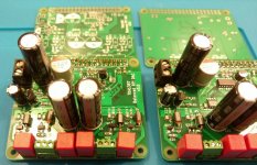
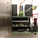
My balanced RPI HAT DAC boards were delivered last night. After the kiddos went to bed, I spent about 2.5 hours stuffing two of them. Not to toot my own horn, but I think this is my best SMD soldering job to date. I'm using the "poor man's reflow" technique, aka, a frying pan on the cooking range. I decided this process is like painting: the final result is dominated by the quality of the setup and preparation. Although, I haven't had a chance to test yet, if significant re-work is required, that will ruin my beautiful SMD job. But at least for now, I can bask in their aesthetic glory!
I will try to remember to measure this tonight. I spent all my time last night on the balanced boards.
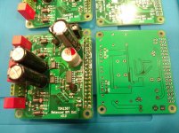
On all the PCBs I've designed, the RCAs are not on-board. On the single-ended board, I just have three holes (left-ground-right). You can direct solder wires to the board or install a screw terminal. Similar story on the balanced board, except six holes (neg-ground-pos, for each channel).
My balanced RPI HAT DAC boards were delivered last night. After the kiddos went to bed, I spent about 2.5 hours stuffing two of them. Not to toot my own horn, but I think this is my best SMD soldering job to date. I'm using the "poor man's reflow" technique, aka, a frying pan on the cooking range. I decided this process is like painting: the final result is dominated by the quality of the setup and preparation. Although, I haven't had a chance to test yet, if significant re-work is required, that will ruin my beautiful SMD job. But at least for now, I can bask in their aesthetic glory!
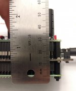
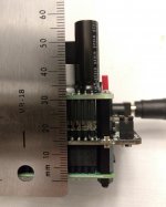
Wondering how tall the stack is with a pi, kali and DAC?
I will try to remember to measure this tonight. I spent all my time last night on the balanced boards.
Since I assume the DAC's RCA jack locations are not identical to any commercial product, I'll probably just go for a simple "dog bone" style acrylic top and bottom with standoffs in between. I guess that leaves it susceptible to dust, though.
On all the PCBs I've designed, the RCAs are not on-board. On the single-ended board, I just have three holes (left-ground-right). You can direct solder wires to the board or install a screw terminal. Similar story on the balanced board, except six holes (neg-ground-pos, for each channel).
Attachments
@stellarelephant, @randytsuch, @luxury54 :
Are you guys interested in giving me some listening feedback if I send you each a built up filter board? Before I spend time building them I'd like some assurance that they'd be going to a good home so do you each have DACs to connect them to or would you also need built up DAC boards to partner them with?
The DAC board has 4*TDA1387 and a simple power supply reg on it. It needs feeding with I2S so to evaluate the pair you'd need an I2S source.
If you'd each let me know your setups (by PM would work best I think) then I'll decide who's best placed to get a piece of the action
Hey 'Braxy,
I've got a NOS TDA1541, NOS 1387 / 1543 and a NOS 1545 and a few different output stages (resistor, tube, Pass, Rudolf Broertjes' SS I/V)
... but they're all single chip DACs, D'oh.
In your circuit, the inductors get huge when scaled for single chip output (1 - 2mA) don't they, crud.
Cheers,
Jeff
P.S. You inspired me to get the old 1387 out!


2706 USB Rx so not NOS
Skyhook I2S cable
TekDev (w batt pwr ~5.5V):
Res I/V 4.69k; back to back coupling cap 22u, 20V; shunt res 160ohm; output (shunt res after output caps so Rout ~ 160ohm)
11.6k, 22u 20V, .1u all in parallel to gnd from Vref.
old, tarnished, cheap Edcor WSM 10k 10k trans out (distortion is high but still sounds ok)
Wattage 0.5W; Input Maximum Voltage 10Vrms; Turns Ratio/Primary (input) Impedance/Secondary (output) Impedance: depends on model; Frequency Response 20~20K Hz., <1dBu; THD+Noise <0.05% @ 1K Hz; Insertion Los 0.5 dB
View attachment WSM10K-10K.pdf
Even though there's some issues and lowish output (guessing ~ 1Vrms), sounds nice!
I'm not noticing a bass roll off from the filt of L of the trans and the Riv when I short the trans out of circuit. I guess the shunt res 160ohm is the R in the R L filter so less bass roll off (and I'll get out my LC meter and measure the trans L).
It's not NOS so the trans is helping to filter the higher images/aliases and providing isolation.
Mods: res i/v too high - use 3.5k; single silmic2 10u, 35V coupling cap; play with Vcc caps; play with shunt res; play with Vref cap (I've got an old Panny HFQ 15,000uf, 6.3V around here somewhere!) and res; add parallel cap to Riv for hf filt; add 20k res on trans output so trans sees ~15-10k output, add rc filt on trans output, ...; batt power to USB - cut USB cable Vcc traces ...
Fun!
Cheers,
Jeff
Last edited:
My balanced RPI HAT DAC boards were delivered last night. After the kiddos went to bed, I spent about 2.5 hours stuffing two of them. Not to toot my own horn, but I think this is my best SMD soldering job to date.
Those look amazingly professional Matt - way to go!
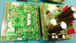
And do I see there J327s used as I/V on one board against BC807s on another? So you're in a position to compare MOSFET vs Bipolar for I/V transistors
How big are those pin7 'lytics? They look enormous!
Wondering how tall the stack is with a pi, kali and DAC?
See attached pics. Looks like board to board height is right at 30mm. For total height, the picture is a bit misleading (lens curvature effect); those electrolytics are 31.5mm tall, so bottom board to top of the tallest cap is 61.5mm. Note that is without any bottom standoffs, which you'll want to add. I'd look for an enclosure that gives you at least 70mm of height.
Also note, the top PCB isn't screwed down, so the board to board height looks a little taller when measured from the front (I circled the gap in red).
Those look amazingly professional Matt - way to go!
Thanks! Unfortunately, that's all they are good for right now: looks. I powered them up last night, no sound at all. What's disconcerting is that the power-on LED doesn't even light up - I can't even get it to light up with my DMM (thinking maybe I soldered it own backwards). But I am getting power. I'm a little worried I left boards on the skillet too long. Anyway, I didn't have any time for debugging, hopefully it's something trivial!
And do I see there J327s used as I/V on one board against BC807s on another? So you're in a position to compare MOSFET vs Bipolar for I/V transistors
Yes sir, that is the plan!
How big are those pin7 'lytics? They look enormous!
They are 10v/2200uF. Nichicon UHE1A222MPD. 10mm diameter, 31.5mm height.
Attachments
Hello,
Great thread and wonderful contributors, much to be appreciated.
Has anyone utilised digipart to source tda1387T chips?
A number of distributors offer stock. Distributors | DigiPart
Regards,
Alistair.
Great thread and wonderful contributors, much to be appreciated.
Has anyone utilised digipart to source tda1387T chips?
A number of distributors offer stock. Distributors | DigiPart
Regards,
Alistair.
Hi all,
For reference/interest, did an RFQ with one of the listed digipart distributors, 1994 Philips TDA1387T surplus new stock, based on the minimum order amount and the stock on hand worked out at $3.13 per chip excl shipping.
I am sure it is possible to source original stock at better pricing, nonetheless it will be a volume based exercise to have any price advantage. That must be seen obvious I guess.
Regards,
Alistair
Well, after a little head-scratching, I'm set up for success. So far I like Volumio.
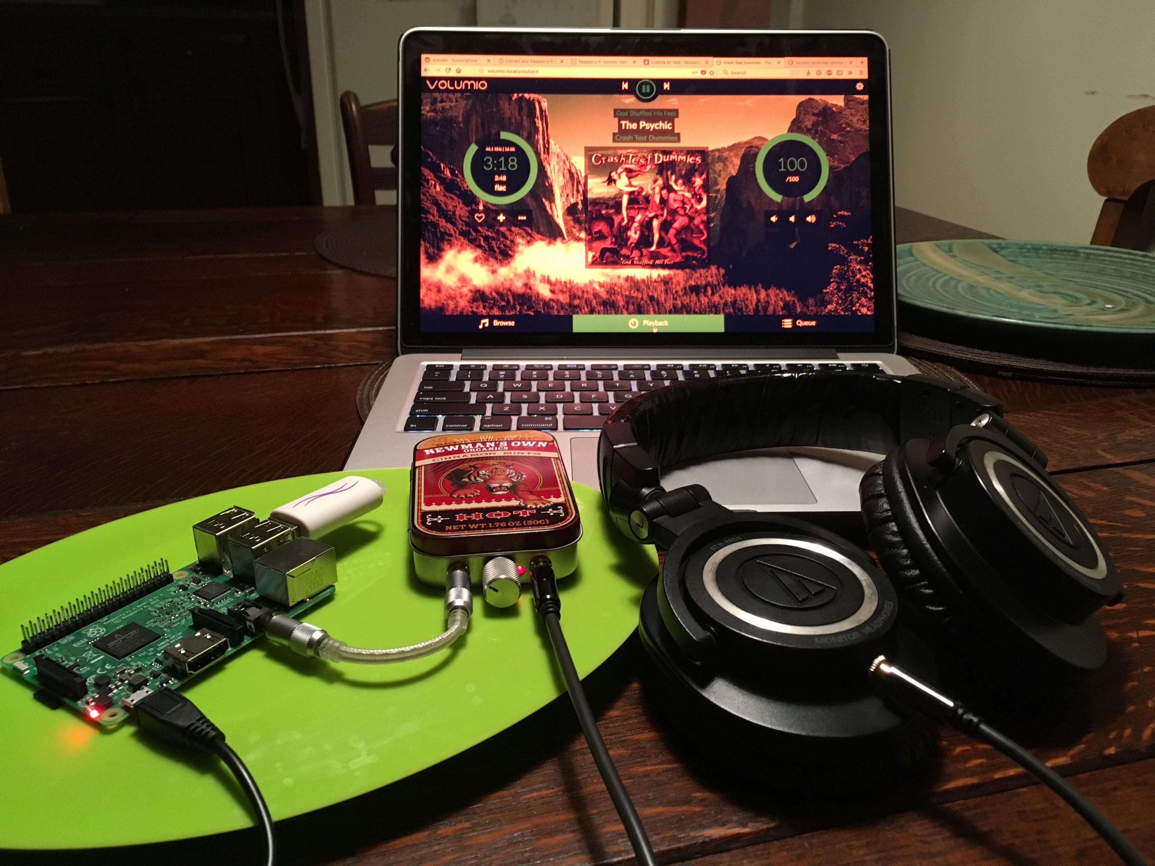
At first I was surprised that the onboard Pi DAC didn't sound quite as attrocious as I expected for a $30 computer. Then I discovered that with bass heavy tracks, it clips badly in the left channel with the digital volume set above 85%. Lol. Time for a Kali and a 1387 front end!
At first I was surprised that the onboard Pi DAC didn't sound quite as attrocious as I expected for a $30 computer. Then I discovered that with bass heavy tracks, it clips badly in the left channel with the digital volume set above 85%. Lol. Time for a Kali and a 1387 front end!
Attachments

Snow day here in the mountains, so I get a free day to stay home and play with Volumio through the stock Pi.
Volumio has three options for volume control: Software, Hardware, and None. I believe the stock setting was Hardware. Today I changed it to None, since I have a pot in front of my Tripath amp, and curiously, the volume instantly dropped by 75% or more. Even stranger is the fact that now when I toggle through the three modes, they are all quiet now. I have tried rebooting the Pi in each mode, but they all remain super quiet with volume set to max. At least the clipping is gone now, but it seems like there is some type of glitch here. Or maybe the glitch was present from first boot and the gain was too high, and I solved it by resetting the volume prefs. But honestly it now seems waaay too quiet to be right.
Hopefully this is a hardware issue, not a Volumio problem, so that it won't have any effect whatsoever when I am using I2S. Can anybody confirm whether the output voltage of their Pi's built-in audio jack is insanely low? Also, what Volumio volume control option do you use in your setup?
Hopefully this is a hardware issue, not a Volumio problem, so that it won't have any effect whatsoever when I am using I2S. Can anybody confirm whether the output voltage of their Pi's built-in audio jack is insanely low? Also, what Volumio volume control option do you use in your setup?
I've never used the RPi's on-board sound, but I have a little experience with sound devices in Linux in general. I have experienced sound devices that behave similar to what you describe. That is, if the volume is turned up too much, there is obvious noise/distortion. I never really dug into this, but I made the assumption that the audio driver (or hardware) must have some kind of "boost" or "extra gain" functionality, which resulted in the "overdriven" sound.
I do everything from the commandline, so I don't know what controls Volumio exposes. But you can definitely learn more about the on-board sound chip's capabilities if you login via ssh to a command prompt. You'll have to familiarize yourself with ALSA, which was designed for everything except user-friendliness.
But you can start with "aplay -L" and/or "aplay -l" (lower case el) to see a list of audio devices that Linux knows about.What will be really interesting is if you use the text-based GUI program "alsamixer", which will show you all the tunables that the on-board sound chip exposes. I have a hunch that you should be able to go in there and tweak the onboard sound for maximum output, while staying below the obvious clipping you're hearing.
The only catch here is that Volumio may revert the changes you make from the commandline. I'm almost certain your manual changes will be lost after a reboot; not sure what will happen if you mess with things at runtime.
If you're comfortable with the commandline, I'd recommend using the DietPi distribution. It's by design a super lightweight/bare minimum SBC Linux distro. It's not targeted explicitly at RPI audio applications, but the audio-centric distros (such as Volumio) start with a stripped-down base OS (or at least they should).
- Home
- Source & Line
- Digital Line Level
- tda1387 dac pcb "front end"