Ok, thanks abraxalito - sounds good, but for now I think I will stick to the original parts and voltages. Damn, I just hope my dac works - I find this smd soldering very challenging and suspect that those J327's might not be soldered properly. Only time will tell.
Stellar - nice build, but not really a child proof enclosure. What other HATS do you have on the Pi that is worthwhile? One looks like a Kali reclocker - if so, how do you find it's added value?
Stellar - nice build, but not really a child proof enclosure. What other HATS do you have on the Pi that is worthwhile? One looks like a Kali reclocker - if so, how do you find it's added value?
I have IanCanada's IsolatorPi on there for removing noise from the RPi. I have been told that Allo's isolator is just as good, if not better. Isolation makes a big difference for stomping out audible hum and hash, and improves background blackness, instrument separation, and stage width. Allo Kali focuses the image a step further. I like separate, LDO regulated linear power rails on all three digital boards, and a simpler full-wave rectified linear supply on the DAC.
Last edited:
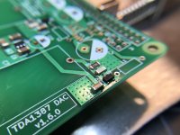
Some good news - I finished populating my board last night, beating pcgab to it.
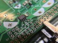
The bad news - only the left channel is working. I quickly hooked it up to a Amanero for testing. I strongly suspect the problem lies with Q1 - one of the J327s. I had a bad feeling after soldering this component. Any ideas how I can trace or confirm this fault?
The bad news - only the left channel is working. I quickly hooked it up to a Amanero for testing. I strongly suspect the problem lies with Q1 - one of the J327s. I had a bad feeling after soldering this component. Any ideas how I can trace or confirm this fault?
Attachments
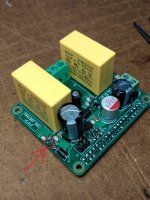
Thank you for the fast response. Left channel measures 0.47V on the I/V resistor. Right channel is dead. So, I assume the soldering of the J327 is faulty?First check I'd make would be the DC level on the I/V resistor for the right channel. This may well give an indication about the fault.
RPi HAT DAC v1.6 working - first sound
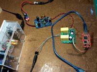
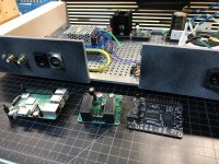
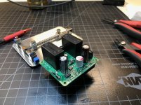
Problem solved! Thank you very much abraxalito for your advice. I actually found two dry joints on the right channel. All is good now and I am absolutely ecstatic.
Here is my test setup. From left to right - Class A Headamp, Low-noise PSU, DAC board, Amanero.
First sound is fantastic - I have never heard so much detail and warmth with "Take Five - Dave Brubeck Quartet". Cannot wait to get it running with the RPi.
Thank you so much Matt for this fantastic project, and for supplying the free board!
Attachments
twocents - glad you got it up and running, and glad you're enjoying it! It's always a delight to see others using my designs, and even more rewarding when it's actually enjoyed. Feel free to ask any more questions you may have.
abraxalito - thank you for helping before I had a chance to reply. You are now officially on tech support duty.")
abraxalito - thank you for helping before I had a chance to reply. You are now officially on tech support duty.
Just an update on my project. I connected (using the socket, not via Amanero USB) the HAT DAC to my Pi today for the first time. The dac board is powered using an external (ultra) low noise psu, while the Pi is still powered using the normal Raspberry wall wart psu. With this setup I can still hear a very very faint hiss on full volume. The Raspberry psu will be replaced with another low noise psu later.
Running Volumio on the Pi, I configured it for I2S output and the Hifiberry DAC option. Seems to work perfectly. I use BubbleUPnP on my Android phone to control the Pi via WiFi. Using BubbleUPnP I can play FLAC files (stored on the phone) or stream from my Google Music playlists. Perfect for my needs.
I am (still and even more) ecstatic! This whole project is a dream come true for me. The dac sounds absolutely beautiful - much more musical and detailed compared to my current Sabre 9018 dac. I have only tested with headphones so far, so I cannot comment on soundstage, imaging, instrument seperation etc. on speakers yet.
Thank you once again Matt for sharing this project with us.
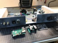
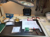
Twocents motivated me to get mine built today.
Hopefully I'll get time this week or next to get it set up in the prototype chassis with my pi 3b+, kali, and separate, regulated power supplies.
Very excited to start listening!
Cheers,
Gable
Hopefully I'll get time this week or next to get it set up in the prototype chassis with my pi 3b+, kali, and separate, regulated power supplies.
Very excited to start listening!
Cheers,
Gable
Attachments
Twocents, congrats! I really love the sound Matt's original 1387 hat over headphones. I look forward to your impressions of the imaging over speakers.
Gable,
Your chassis looks very nice. Cool that you have preserved all of the Pi's connectivity options. Are you going to include an antenna for WiFi, or will you strictly use Ethernet? I have modified the 3b+ with an external antenna and can post details and pics if anybody is interested. I even have a few leftover U.FL sockets and shielded antenna cables to share...
I hope to start putting together a Digikey cart for this project over the weekend...
Last edited:
Twocents, congrats! I really love the sound Matt's original 1387 hat over headphones. I look forward to your impressions of the imaging over speakers.
Gable,
Your chassis looks very nice. Cool that you have preserved all of the Pi's connectivity options. Are you going to include an antenna for WiFi, or will you strictly use Ethernet? I have modified the 3b+ with an external antenna and can post details and pics if anybody is interested. I even have a few leftover U.FL sockets and shielded antenna cables to share...
I hope to start putting together a Digikey cart for this project over the weekend...
Ultimately, I will likely use ethernet only. However, I have some usb wifi adapters that I've used with other pi's and may test one or two of those.
I would love to see your modified 3b+ antenna setup.
Cheers,
Gable
I am going with Mouser for parts, mainly for ease of ordering with Matt's BOM. I'm still kicking around my final parts decisions with my friend Greg Stewart, but hope to order soon. I think we are going to use the full 2K7 value for our I/V resistors to get max output...Susumu RG series most likely.
As for the Raspberry Pi antenna mod, here are the links that I used myself to get going:
DIYA Member Bvlabs posted some great pics and a link here.
and
This hackaday tutorial describes the mod well too.
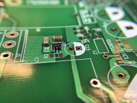
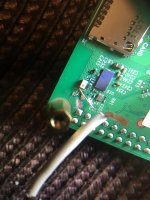
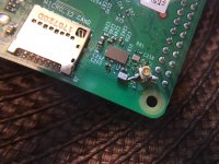
Scratching the mask for mounting the U.FL socket is easy. The zero ohm 0201 resistors, however, are on the verge of invisibility. You only have to remove one of them to break the connection to the on-board antenna. You could reuse it to make the connection to the new socket, but it was so infuriatingly tiny, I just threw it out and used a single strand of copper wire to go directly from the vacated solder pad to the socket terminal. My phone pics aren't great, but here they are.
If you aren't using an isolator in you Rpi stack, you WILL hear more WiFi noise leaking into your audio than you did before...for me it is roughtly 2-3x as loud, and I am only using a 3dbi antenna. With an isolator, it is completely gone--just as silent as before the mod. I plan to take the isolator out at some point and see what a ferrite snap bead can do on its own...
As for the Raspberry Pi antenna mod, here are the links that I used myself to get going:
DIYA Member Bvlabs posted some great pics and a link here.
and
This hackaday tutorial describes the mod well too.
Scratching the mask for mounting the U.FL socket is easy. The zero ohm 0201 resistors, however, are on the verge of invisibility. You only have to remove one of them to break the connection to the on-board antenna. You could reuse it to make the connection to the new socket, but it was so infuriatingly tiny, I just threw it out and used a single strand of copper wire to go directly from the vacated solder pad to the socket terminal. My phone pics aren't great, but here they are.
If you aren't using an isolator in you Rpi stack, you WILL hear more WiFi noise leaking into your audio than you did before...for me it is roughtly 2-3x as loud, and I am only using a 3dbi antenna. With an isolator, it is completely gone--just as silent as before the mod. I plan to take the isolator out at some point and see what a ferrite snap bead can do on its own...
Attachments
Last edited:
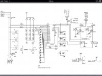
Sorry, previous post was the wrong schematic. (Previous is the balanced RPI Hat.) Here's the right one!
Moderators, please feel free to delete the previous post.
I refer to the schematic for version 1.2.
Forgive my ignorance, but what are jumpers J3 and J4 for? I had some boards made from the gerbers and I believe that when I checked the traces for continuity, one of the pads, I cannot remember which offhand, but J4 I believe, had no connection to the ground of the RPI.
Are the jumpers to be closed or left open?
Please clarify. Thanks in advance
I like the transparency and simplicity of ground gate current buffer used in the Red baron TDA 1541 board.
Will it work if I attached the output from TDA 1387 to 2SK 216 circuit posted below ??
Is there other alternative to 2SK 216 ?
No problem asking that question in this thread, but I'm afraid I don't have enough knowledge to give any kind of useful answer. Unless someone else pipes up, you might want to take the question to another thread if only to get more eyes on it.
I refer to the schematic for version 1.2.
Forgive my ignorance, but what are jumpers J3 and J4 for? I had some boards made from the gerbers and I believe that when I checked the traces for continuity, one of the pads, I cannot remember which offhand, but J4 I believe, had no connection to the ground of the RPI.
Are the jumpers to be closed or left open?
They need to be closed. There are three different grounds on the v1.2 design, J3 and J4 tie them all together. (I got away from that in later versions and just had one big common 0v reference.) But yes, when those jumpers are open, you won't see any continuity to RPI ground.
Hope that helps!
Problem solved! Thank you very much abraxalito for your advice. I actually found two dry joints on the right channel. All is good now and I am absolutely ecstatic.
Here is my test setup. From left to right - Class A Headamp, Low-noise PSU, DAC board, Amanero.
First sound is fantastic - I have never heard so much detail and warmth with "Take Five - Dave Brubeck Quartet". Cannot wait to get it running with the RPi.
Thank you so much Matt for this fantastic project, and for supplying the free board!
twocents, Nice setup. I might try the same. I have received my SE 1.6 boards and components, Amanero USB2I2S is on the way (for my Soekris DAM1021 build).
I need some help to understand the connections J4 -> Amanero :
1. I am confused with I2S_WS (from the schematics), if its to be connected to CLK or FSCLK on Amanero?
2. Also, as per schematics, 1-3-5 pins on J4 are to be connected GND. Did you connect all of these to Amanero GND pins.
TIA
I actually borrowed the Amanero from a friend just to test my DAC before connecting to the RPi. So, I cannot check physically anymore, but I made a note somewhere that WS connects to FSCLK on the Amanero. For GND you only need to connect one of the three pins on the PCB to the Amanero GND. So, only 4 connections. Hope that helps.I need some help to understand the connections J4 -> Amanero :
1. I am confused with I2S_WS (from the schematics), if its to be connected to CLK or FSCLK on Amanero?
2. Also, as per schematics, 1-3-5 pins on J4 are to be connected GND. Did you connect all of these to Amanero GND pins.
- Home
- Source & Line
- Digital Line Level
- tda1387 dac pcb "front end"