Does anyone know whether the single bit stream of a DSD signal is to be interpreted as:
A. Just a series of simple unsigned bits, so 1 > 0
or
B. A stream of sign bits of very short two's complement words, so 1 means negative and 0 means not negative?
I've always assumed A, but that's not based on anything, and a colleague of mine tends to see sigma-delta modulates as rows of single-bit signed numbers.
My apologies for posting this twice; I had accidentally put it in the wrong forum and didn't manage to delete it anymore.
I think DSD is a hybrid between analog and digital. You can regard DSD as an analog signal and convert it to the original signal by simple RC filter. If you regard
DSD as digital one, you design decimation filter to remove HF. Both are theoretically possible to reproduce the original one.
But in a practical solution, I prefer a digital one. I once struggled with a simple solution which converts DSD to analog without a commercial DACs like pcm1792. It means a DAC without DAC chips. I finally gave up. Achieving the performance like pcm1792 is tough by a 1bit converter.
I'm not sure the reason why. The fatal issue probably comes from rise and fall time of analog output. SIM of DSD in digital domain has no rise and fall time. It's excellent performance indeed. But you can't get good SNR in a real circuit. Rise and fall time is something like a glitch which degrades SNR. The amplitude of this glitch is an inverse proportion to bit resolution. DSD is the worst because it always swings from the min to the max or the opposite direction.
I'm not sure low SNR comes from 1 bit. But 2bit is better than 1bit. 5bit or more resolution can outperform pcm1792 even in 1bit operation. If your DSM DAC is 5bits resolution, it forces to work in 1bit when the input is below about 50dB. But the voltage swing is smaller than DSD by 1/32 because their LSB is 1/32. In this case, no degradation of SNR occurs. That's why I think DSD has the fatal problem to be implemented into a simple RC converter.
The rise and fall time issue should be solved when you make a return-to-zero DAC. Did you try that? The simplest return-to-zero DAC is a D flip-flop with a NOR gate after it that suppresses the output while the clock is high. You can improve it further by making a FIRDAC, combining a digital delay line and a few elementary DACs of which the outputs are added.
Even then you won't get close to the SNR values of the best commercial DAC chips. You would need a switched capacitor DAC and/or a really long FIRDAC and/or an extremely good clock for that.
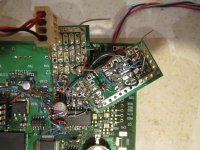
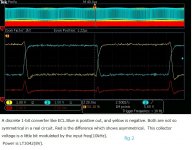
As an example of a simple return-to-zero FIRDAC, the attachment is a circuit I'm building. It is a four-tap uniformly weighted FIRDAC with an active low-pass filter behind it. It isn't meant for DSD but for the sigma-delta from the "Clarification of Sigma Delta DAC operation wanted" thread, but with other filter component values it could also be used for DSD. I make it balanced to cancel out the effect of unequal high and low output resistances of the logic gates. The supply for the logic gates comes from a LTC3042 low-noise voltage regulator with a ferrite bead-capacitor filter behind it.
Even then you won't get close to the SNR values of the best commercial DAC chips. You would need a switched capacitor DAC and/or a really long FIRDAC and/or an extremely good clock for that.
As an example of a simple return-to-zero FIRDAC, the attachment is a circuit I'm building. It is a four-tap uniformly weighted FIRDAC with an active low-pass filter behind it. It isn't meant for DSD but for the sigma-delta from the "Clarification of Sigma Delta DAC operation wanted" thread, but with other filter component values it could also be used for DSD. I make it balanced to cancel out the effect of unequal high and low output resistances of the logic gates. The supply for the logic gates comes from a LTC3042 low-noise voltage regulator with a ferrite bead-capacitor filter behind it.
Attachments
Thank you for your suggestion. Many people around me are a consumer, those who are interested in DIY hardware is rare. I can't get interesting information about DIY even on the internet in Japanese. As long as I know, return to zero is one solution to decrease glitches of a multi-bit DAC because RTZ can cancel different delay of each segment. I can't exactly understand that RTZ has the same effect about 1bit DSM.
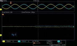
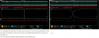
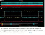
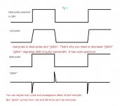
What I want to mean in rise and fall time is the difference between ideal pulse and a real one like fig 1. A real pulse has finite rise and fall time. They act as something like a glitch which causes degradation of SNR. Shorter rise/fall time is needed for high SNR more than 100dB. As long as I tested, 1bit converter can't achieve this goal. fig2,fig3,fig4, and fig5 are several attempts I have ever done.
My conclusion is that this type of glitch is the inverse proportion to bit resolution. That's why 1bit can't be superior to a multi-bit. 1bit always has 100% voltage swing. This is the worst situation for "glitch." If you use 5bit, the amplitude of "glitch" becomes 1/32. Those data is measured with the attached pic. I'm going to design a new prototype PCB for this DSM. I can test both 1bit and multi-bit DSM with the new PCB. I'm sure 1bit is almost same as my terrible breadboard.")
What I want to mean in rise and fall time is the difference between ideal pulse and a real one like fig 1. A real pulse has finite rise and fall time. They act as something like a glitch which causes degradation of SNR. Shorter rise/fall time is needed for high SNR more than 100dB. As long as I tested, 1bit converter can't achieve this goal. fig2,fig3,fig4, and fig5 are several attempts I have ever done.
My conclusion is that this type of glitch is the inverse proportion to bit resolution. That's why 1bit can't be superior to a multi-bit. 1bit always has 100% voltage swing. This is the worst situation for "glitch." If you use 5bit, the amplitude of "glitch" becomes 1/32. Those data is measured with the attached pic. I'm going to design a new prototype PCB for this DSM. I can test both 1bit and multi-bit DSM with the new PCB. I'm sure 1bit is almost same as my terrible breadboard.
Attachments
Does anyone know whether the single bit stream of a DSD signal is to be interpreted as......
1. The bits are given as "1" or "0".
2. This means as level as +1 or -1.
3. To have an idle level, a certain bit sequence is used.
4. To go positive on level: more "1" bit's are used in compare to go negative on level: more "0" bits are used.
Currently on building my DSD generator & analyzer
Hp
Thank you for your suggestion. Many people around me are a consumer, those who are interested in DIY hardware is rare. I can't get interesting information about DIY even on the internet in Japanese. As long as I know, return to zero is one solution to decrease glitches of a multi-bit DAC because RTZ can cancel different delay of each segment. I can't exactly understand that RTZ has the same effect about 1bit DSM.
What I want to mean in rise and fall time is the difference between ideal pulse and a real one like fig 1. A real pulse has finite rise and fall time. They act as something like a glitch which causes degradation of SNR. Shorter rise/fall time is needed for high SNR more than 100dB. As long as I tested, 1bit converter can't achieve this goal. fig2,fig3,fig4, and fig5 are several attempts I have ever done.
My conclusion is that this type of glitch is the inverse proportion to bit resolution. That's why 1bit can't be superior to a multi-bit. 1bit always has 100% voltage swing. This is the worst situation for "glitch." If you use 5bit, the amplitude of "glitch" becomes 1/32. Those data is measured with the attached pic. I'm going to design a new prototype PCB for this DSM. I can test both 1bit and multi-bit DSM with the new PCB. I'm sure 1bit is almost same as my terrible breadboard.
100 dB is quite ambitious, but I look at the glitch problem in a different way,
What matters in the end is the low-pass filtered signal. Low pass filtering means taking a weighted average, where the weight is defined by the impulse response of the filter. Looking over a time span that is much shorter than the reciprocal of the cut-off frequency, the weight is nearly constant.
The problem is that with unequal tPLH and tPHL, the average of a 1010 sequence differs from the average value of a 1100 sequence, as you can see in the attached figure. That is, your bit weights depend on the surrounding bits. By always returning to zero you circumvent this.
The disadvantage is that you get more transitions, which makes you more sensitive to slight displacements of these transitions, caused by things like clock jitter. A FIRDAC can solve that again.
Multibit is indeed also an option. If your sigma-delta indeed only uses two levels during silence, mismatch will only show up in the distortion figures and not in the ratio between maximum signal and idle channel noise.
Attachments

Last edited:
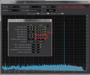
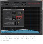
You can regard glitch as impulse whose spectrum spreads equally from DC to HF like white noise. LPF can only remove its HF above the audio band. I'm sure once glitch occurs, its audio band noise degrades SNR. Attached pics are SNR data of 1bit, 2bit, and 5bit DSM. I think small glitch amplitude is critical for high SNR from my data.
Attachments
As an example of a simple return-to-zero FIRDAC, the attachment is a circuit I'm building. It is a four-tap uniformly weighted FIRDAC with an active low-pass filter behind it. It isn't meant for DSD but for the sigma-delta from the "Clarification of Sigma Delta DAC operation wanted" thread, but with other filter component values it could also be used for DSD. I make it balanced to cancel out the effect of unequal high and low output resistances of the logic gates. The supply for the logic gates comes from a LTC3042 low-noise voltage regulator with a ferrite bead-capacitor filter behind it.
Hi, I finally understand what you mean. I found a discrete DSM DAC DSC1 made by Signalyst. It uses 32 registers to implement 32taps sinc filter for removal of HF noise. It makes sense. I have never thought about this method. But this is the similar way of pcm1792 which has 64taps FIR filter for DSD. That was a blind spot for me.
As long as I know so far, those who want to convert DSD to analog signal uses simple LPF without a series registers. I also tried in the same way. It didn't work well as I wrote before. If you use such a method, glitch problem is not so critical than a simple LPF.
Have you ever measured the circuit which you posted? I have found several data about DSC1. I don't know what performance it has because accurate values depend on measurement circumstance. The exclusive input to DSD isn't so inconvenient. I don't know why this is less attractive than a discrete multi-bit.
You can regard glitch as impulse whose spectrum spreads equally from DC to HF like white noise. LPF can only remove its HF above the audio band. I'm sure once glitch occurs, its audio band noise degrades SNR. Attached pics are SNR data of 1bit, 2bit, and 5bit DSM. I think small glitch amplitude is critical for high SNR from my data.
I think we agree about the advantages of multibit converters, but I still disagree with your analysis of glitches.
It is true that a glitch also has low-frequency content, but that is not necessarily a problem. For a single-bit converter, as long as all ones have the exact same waveform and all zeroes have the exact same waveform, and the waveform of the ones has a different average value than the waveform of the zeroes, everything is OK. Whether the waveforms for one and zero contain glitches then doesn't matter. For example, if all ones have the same glitch, the area of the glitch simply adds to the area of the waveform and produces a gain error, but that's it.
You get problems when some ones have a different waveform than other ones, or when some zeroes have a different waveform than other zeroes. For example, when a non-return-to-zero DAC produces a glitch at a 0-to-1 transition but not at a 1-to-1 transition.
Hi, I finally understand what you mean. I found a discrete DSM DAC DSC1 made by Signalyst. It uses 32 registers to implement 32taps sinc filter for removal of HF noise. It makes sense. I have never thought about this method. But this is the similar way of pcm1792 which has 64taps FIR filter for DSD. That was a blind spot for me.
As long as I know so far, those who want to convert DSD to analog signal uses simple LPF without a series registers. I also tried in the same way. It didn't work well as I wrote before. If you use such a method, glitch problem is not so critical than a simple LPF.
Have you ever measured the circuit which you posted? I have found several data about DSC1. I don't know what performance it has because accurate values depend on measurement circumstance. The exclusive input to DSD isn't so inconvenient. I don't know why this is less attractive than a discrete multi-bit.
There is an interesting patent on FIRDACs. As far as I know it has passed its due by date, so you can even use FIRDACs commercially. Like most US patents, you can easily find it on the internet.
Heinrich Pfeifer, Werner Reich and Ulrich Theus, Circuit arrangements for averaging signals during pulse-density D/A or A/D conversion, US patent 4947171, 7 August 1990
A nice feature of FIRDACs is that mismatch between the weights of the taps only reduces the stop band suppression, but doesn't cause distortion or noise folding.
I haven't measured the circuit I posted yet because I'm still soldering the components on the board. An earlier two-tap RTZ FIRDAC I made with E88CC thermionic valves has a noise floor of -85.76 dB(A) on the left and -91.29 dB(A) on the right channel with respect to a full-scale sine wave, working with the sigma-delta modulator that I posted in the 'Clarification of Sigma Delta DAC operation wanted'-thread.
Last edited:
very interesting theory
Thank you for your information. I searched DSC1 on eBay but couldn't find the original one. I only found two kinds of china clone which are probably a compatible one. It's worth paying to examine how is the performance. It's true as long as "one" is an ideal square wave, the tolerance of resistors has almost nothing to do with THD as you write. That's the point of this method.
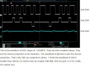
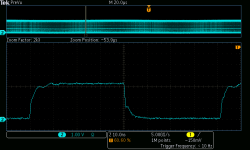
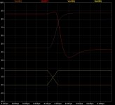
Typical gate ICs have different tplh and tphl. High-speed ones often have something like ringing. Attached is TC7WZ04FK(propagation delay 2.3nS) which I used for DSD. If you use a simple FIRDAC consist of two registers and the input data is "10". The next clock shifts data to "01". "10" is blue of attached fig 3."01" is yellow.
SIM assumes exact "10" and "01". It means the average value is always 0.5. Because (1+0)/2=(0+1)/2=0.5. But in a real circuit, the different tplh and tphl make some error like red. I think what you can get in a real PCB is the ideal value(0.5) and error something like a glitch. FIRDAC with 32 registers or more can decrease this side effect. The differential type also can decrease. But I don't know how extent they can reduce the side effect. That's why I need to measure in a real PCB.
Thank you for your information. I searched DSC1 on eBay but couldn't find the original one. I only found two kinds of china clone which are probably a compatible one. It's worth paying to examine how is the performance. It's true as long as "one" is an ideal square wave, the tolerance of resistors has almost nothing to do with THD as you write. That's the point of this method.
Typical gate ICs have different tplh and tphl. High-speed ones often have something like ringing. Attached is TC7WZ04FK(propagation delay 2.3nS) which I used for DSD. If you use a simple FIRDAC consist of two registers and the input data is "10". The next clock shifts data to "01". "10" is blue of attached fig 3."01" is yellow.
SIM assumes exact "10" and "01". It means the average value is always 0.5. Because (1+0)/2=(0+1)/2=0.5. But in a real circuit, the different tplh and tphl make some error like red. I think what you can get in a real PCB is the ideal value(0.5) and error something like a glitch. FIRDAC with 32 registers or more can decrease this side effect. The differential type also can decrease. But I don't know how extent they can reduce the side effect. That's why I need to measure in a real PCB.
Attachments

Another weakness of 1bit is PSRR or reference supply noise, isn't it? 1bit modulates their noise interleaved manner, so no common mode, to differential output. Multibit modulates them fully common at zero signal : canceled by CMR , up to fully differential at full scale DC.
Yes, that's true for high-frequency reference noise. Another way to describe it is to say that reference noise gets multiplied by the sigma-delta modulate and that this multiplication can frequency-convert out-of-band reference noise to low frequencies. Low-frequency reference noise (say << 20 kHz) only gives sidebands around the desired signal, as it does in any DAC, and sidebands around the out-of-band quantization noise that you need to filter off anyway.
This effect can be reduced by filtering the reference to get rid of high-frequency noise and by making a FIRDAC. Filtering the reference is easy, but when you have any crosstalk from the sigma-delta modulate to the filtered reference, the noise floor goes up again.
This effect can be reduced by filtering the reference to get rid of high-frequency noise and by making a FIRDAC. Filtering the reference is easy, but when you have any crosstalk from the sigma-delta modulate to the filtered reference, the noise floor goes up again.
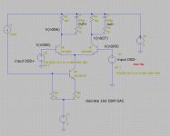
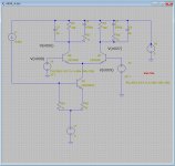
I can't exactly understand what your suggestions mean, probably because we use the different circuit.Here is the schematic and SIM of my discrete 1bit DSD DAC. This is a simple conversion from differential DSD(V(n008) and V(n009)) powered by digital Vdd(FPGA) to another voltage reference(9V powered by lt3042). Analog outputs are out+ and out-, which are buffered by an opamp.
I think out+ and out- can theoretically cancel even order distortions and other common mode disturbances. I know of course this is head knowledge, practically doesn't work well as I intend. Unfortunately, it was true in this case.
Another disadvantage of 1bit is less efficiency of voltage swing. The max efficiency of 1bit is 50% at max. e.g., you can get the 2V analog signal from the 4V swing. This is the limitation of high order 1bit DSM. More than 4bits can utilize almost 100%. It means 1bit has inherent loss of 6db SNR. This is fatal if you want high SNR more than 100dB, IMHO.
Attachments
There will be some noise on the collector current of Q2. For example, consider the noise between 990 kHz and 1.01 MHz. The sigma-delta modulate will have lots of quantization noise everywhere except in its signal band, so it also has lots of quantization noise between 990 kHz and 1.01 MHz.
The differential pair Q6-Q7 will act as a mixer in the RF sense of the word: circuit that generates sum and difference frequencies. The 990 kHz to 1.01 MHz collector current noise and the 990 kHz to 1.01 MHz quantization noise of the sigma-delta modulate then produce difference frequencies between 0 and 20 kHz.
Hence, out of band reference noise is converted into audio noise. 1 MHz was, of course, only an example, I could have used any frequency outside the signal band of the sigma-delta.
In your circuit you could decouple R9 to get rid of its thermal noise and the noise on I1. I also wonder how much crosstalk you are going to get from the FPGA supply through the base-collector capacitances of Q6 and Q7; you could put a flip-flop in between that runs on a filtered supply.
Last edited:
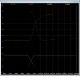
Q6 and Q7 are emitter coupled pair without a register, which has a large gain and is driven by digital logic. So, their analog response is very limited period only at the transition of V(n008) and V(n009), almost 1 nano-sec. Except for that time, they are on or off, don't act as an analog device. I think they can't be a mixer.
My SIM uses ideal inputs V(n008) and V(n009) which comes from FPGA. But almost every output of a digital circuit has the different tplh and tphl. It's practically impossible to have an ideal differential output like SIM. FPGA has internal PLL with being capable of phase adjust by 30 pico-sec step. You can utilize this function to cancel the difference between tplh and tphl. If this adjustment is out of range, SNR becomes far less than with adjustment. 1 nano sec difference usually causes more than 10db degradation of SNR.
As long as I have tested, the most dominating factor to degrade SNR of 1bit DSM is the difference between tplh and tphl. You must adjust this as possible as you can. Multi-bit DSM is free of this problem because they treat an input as a digital one, on the other hand, 1 bit DSM treats an input as an analog one.
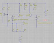
The constant current source of a breadboard is like attached. SIM is mainly for verification of collector voltage, how fast they can swing. So I use a simple CCS. A bypass condenser crossing R9 is also necessary on a real PCB. Crosstalk from base to a collector is probably neglectable. Because of noise on DSD+ or DSD- are relatively low and R2 and R5 are low compared with base-collector capacitance. The attached pic includes floating capacitances of C5 and C6. With 3pF capacitance, collector voltage is almost same as the real one.
My SIM uses ideal inputs V(n008) and V(n009) which comes from FPGA. But almost every output of a digital circuit has the different tplh and tphl. It's practically impossible to have an ideal differential output like SIM. FPGA has internal PLL with being capable of phase adjust by 30 pico-sec step. You can utilize this function to cancel the difference between tplh and tphl. If this adjustment is out of range, SNR becomes far less than with adjustment. 1 nano sec difference usually causes more than 10db degradation of SNR.
As long as I have tested, the most dominating factor to degrade SNR of 1bit DSM is the difference between tplh and tphl. You must adjust this as possible as you can. Multi-bit DSM is free of this problem because they treat an input as a digital one, on the other hand, 1 bit DSM treats an input as an analog one.
The constant current source of a breadboard is like attached. SIM is mainly for verification of collector voltage, how fast they can swing. So I use a simple CCS. A bypass condenser crossing R9 is also necessary on a real PCB. Crosstalk from base to a collector is probably neglectable. Because of noise on DSD+ or DSD- are relatively low and R2 and R5 are low compared with base-collector capacitance. The attached pic includes floating capacitances of C5 and C6. With 3pF capacitance, collector voltage is almost same as the real one.
Attachments
- Status
- This old topic is closed. If you want to reopen this topic, contact a moderator using the "Report Post" button.
- Home
- Source & Line
- Digital Line Level
- Is DSD signed or unsigned?