I have a question to any well educated person in the field.
Let's compare a multibit DAC such as the PCM1794 with a Sigma Delta such as PCM1794. They both handles 24 bits.
The Sigma Delta constructors use to tell us that their algorithms assures that the measured THD and other figures are similar to a multi bit converter.
OK, but I'm not willing to surrender yet. See it this way.
The PCM 1704(multibit) can ( at an SR of lets say 44.1 khz ) output a signal at 22.05 khz and will theoretically let the signal have an amplitude of exact one LSB which is around -144 db. And you should - in a perfect world - be able to detect it.
On the other hand, the PCM1794, which is a 6 bit DAC that adds the remaining lower 18 bits by Sigma Delta algorithms that runs at 64 fs.
Now the interesting thing. The S/D DAC can't ( instantly between two samples ) give more than 64 levels since it operates in 64fs, but of course it can, seen from an averaging point of view, over a longer time span. So this DAC ( if supplied with exactly the same signal as the PCM1704 ) can't represent more than 2^6 x 64 levels = 4096 levels. And that's only 72db.
Remember that we here are talking about a tiny signal that changes only one LSB every sample.
But the really tricky thing is that the S/D will give the same THD as the multibit. Now we are talking about static tones. But the S/D can't handle all the hf nuances that the multibit can.
So from my point of view the S/D probably will output the exact same signal if we feed it with a 22khz/10LSB signal as if we fed it a 22khz/ 2LSB signal.
Or am I wrong?
Personally I think the PCM1792 and other combined multibit/SD DAC's gives a performance that simply is good enough, but the constructors don't really want us to see things this way.
It's not easy to find specimens of PCM1704 these days. it's a pity since I think it's just the champ. Or does someone know of other multi bit devices?
So, are hard core audiophiles becoming more and more rare?
Hi
Sadly you have not named the delta Sigma DAC chip, rather your post compares PCM 1794 with PCM1794 http://www.ti.com/lit/ds/symlink/pcm1794.pdf The PCM1792 that you also mention also is not a Delta Sigma device, http://www.ti.com/lit/ds/symlink/pcm1792.pdf and neither is the PCM1702 . And the PCM 1704 is now discontinued.
Rather delta sigma is usually used to convert analog signals into digital, A/D but can find application also in DAC's , converting digital signals into lower bit count ones.
From what I observe Analog Devices rather than TI are flying the flag ,so to speak for Delta Sigma modulation
Historically i think, Bob Adams was amongst the first to use Delta Sigma modulation in the dbx 700
that dates back to 1983
No hard core audiophiles - a ever growing population, are just more hard core
Last edited:
D-S, higher Ovesampling, Higher Order Modulators do way better than averaging
the power of Delta Sigma comes with higher order modulators and high oversampling ratios
the PCM1794 uses a minimum of 128xfs clock - lets suppose its squared up by a divide by 2 giving 64 OSR
the 'noise shaping' filter pass band bit resolution gain factor with modulator order MO is
~ OSR**(MO +1 / 2)
popular multibit Audio DAC MO are 2, 3 and higher (single bit 'BitStream' DAC may have 5 th Order modulators)
going with MO = 3 and OSR = 64 we get 21 bits of enhancement over the 6 bit current dac for a total of 27 theoretical bits of resolution in the audio band
Last edited:
It's not easy to find specimens of PCM1704 these days. it's a pity since I think it's just the champ. Or does someone know of other multi bit devices?
PCM1702 is regarded by many as better subjectively and not so crazily priced on the secondary market.
If you don't need more than 16bits, TDA1387 is a couple of orders of magnitude cheaper.
about DSM
DSM is not easy to understand like PCM because it is based on mathematical theory.The good textbook is "Understanding Delta-Sigma Data Converter" by Richard Schreier.This is only a map to enter the world of SDM.You need to analyze the true meaning of DSM by yourself with an assistance of this book.
That's why DSM is not popular for DIYers.
One example of the difference between PCM and DSM is the concept of bit resolution.PCM has its own resolution like 16 or 24.DSM doesn't have inherent one like PCM.It probably depends on the input signal and OSR as long as I know.Because I can design DSM with infinite resolution theoretically, especially in the digital domain.DSM output will normally converge to the input signal.This is irrelevant to bit resolution of DSM.
24bits PCM can handle from 8388608 to -8388608.But it can't do 8388607.5.PCM has its inherent limitation.
If you are in DSM domain, you can easily output 8388607.5 by repetition of 8388608 and 8388607.It actually equal to 8388607.5.In 23bits resolution, you have 8388608 and 8388606. 8388607.5 is three 8388608 and one 8388606.
The important thing is DSM will not discard quantization error like PCM.The quantization error is accumulated and to be used for next data calculation.That's why DSM is the convergent system.I think this is the principle of DSM.
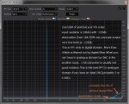
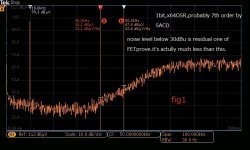
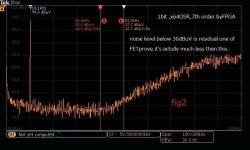
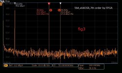
I'm now under consideration to design "discrete DSM DAC" not "discrete multi bit DAC".It means to make DSM DAC like pcm1792 by discrete parts, multi-bit DAC and FPGA for modulation. It has almost finished both digital and analog domain.Here's some data about DSM.
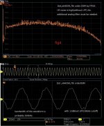
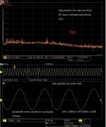
1 bit DSM is used by SACD(DSD).SACD was developed at late 90's.The modulator of SACD is a little bit out of date compared with the latest one which is described in the book above.Quantization noise of SACD is less by almost 10dB(fig1 and fig2).fig 3 is 5bits DSM.Quantization noise is very low.I guess pcm1792 is almost like this.
fig4 and fig 5 are quantization noise of 1bit and 5bits.If you use 5bits, simple 12db/oct filter is adequate enough to remove HF noise.
SNR and THD are another issues.I don't have fixed 4 layer PCB yet.I have no choice now except a bread board to measure.But I'm sure a good solution for SNR is high-speed DAC(more than 200M/s) and external calibration for THD.Both methods and 4 layer PCB can overcome pcm1792 or more IMHO.
DSM is not easy to understand like PCM because it is based on mathematical theory.The good textbook is "Understanding Delta-Sigma Data Converter" by Richard Schreier.This is only a map to enter the world of SDM.You need to analyze the true meaning of DSM by yourself with an assistance of this book.
That's why DSM is not popular for DIYers.
One example of the difference between PCM and DSM is the concept of bit resolution.PCM has its own resolution like 16 or 24.DSM doesn't have inherent one like PCM.It probably depends on the input signal and OSR as long as I know.Because I can design DSM with infinite resolution theoretically, especially in the digital domain.DSM output will normally converge to the input signal.This is irrelevant to bit resolution of DSM.
24bits PCM can handle from 8388608 to -8388608.But it can't do 8388607.5.PCM has its inherent limitation.
If you are in DSM domain, you can easily output 8388607.5 by repetition of 8388608 and 8388607.It actually equal to 8388607.5.In 23bits resolution, you have 8388608 and 8388606. 8388607.5 is three 8388608 and one 8388606.
The important thing is DSM will not discard quantization error like PCM.The quantization error is accumulated and to be used for next data calculation.That's why DSM is the convergent system.I think this is the principle of DSM.
I'm now under consideration to design "discrete DSM DAC" not "discrete multi bit DAC".It means to make DSM DAC like pcm1792 by discrete parts, multi-bit DAC and FPGA for modulation. It has almost finished both digital and analog domain.Here's some data about DSM.
1 bit DSM is used by SACD(DSD).SACD was developed at late 90's.The modulator of SACD is a little bit out of date compared with the latest one which is described in the book above.Quantization noise of SACD is less by almost 10dB(fig1 and fig2).fig 3 is 5bits DSM.Quantization noise is very low.I guess pcm1792 is almost like this.
fig4 and fig 5 are quantization noise of 1bit and 5bits.If you use 5bits, simple 12db/oct filter is adequate enough to remove HF noise.
SNR and THD are another issues.I don't have fixed 4 layer PCB yet.I have no choice now except a bread board to measure.But I'm sure a good solution for SNR is high-speed DAC(more than 200M/s) and external calibration for THD.Both methods and 4 layer PCB can overcome pcm1792 or more IMHO.
Attachments
You're basically asking how much the signal to noise ratio can be improved with noise shaping. If you are very good at mathematics, you can find the complete answer in: Michael A. Gerzon and Peter G. Craven, "Optimal noise shaping and dither of digital signals", Audio Engineering Society preprint 2822, presented at the 87th convention, October 1989.
In a nutshell, noise shaping reduces the noise in one part of the spectrum by increasing it somewhere else. When you plot the change in noise density versus frequency with a linear frequency scale and a vertical dB scale, with the frequency scale extending from 0 to half the sigma-delta clock rate, the area below the 0 dB line (where you get a noise reduction) cannot be larger than the area above the 0 dB line (where you get a noise increase). For a multibit sigma-delta with stable loop filter, the areas are equal.
In a nutshell, noise shaping reduces the noise in one part of the spectrum by increasing it somewhere else. When you plot the change in noise density versus frequency with a linear frequency scale and a vertical dB scale, with the frequency scale extending from 0 to half the sigma-delta clock rate, the area below the 0 dB line (where you get a noise reduction) cannot be larger than the area above the 0 dB line (where you get a noise increase). For a multibit sigma-delta with stable loop filter, the areas are equal.
I'm now under consideration to design "discrete DSM DAC" not "discrete multi bit DAC".It means to make DSM DAC like pcm1792 by discrete parts, multi-bit DAC and FPGA for modulation. It has almost finished both digital and analog domain.
Sounds like an interesting project! Is it going to be a DIY friendly design?
I designed and built my own sigma-delta DAC, wrote an article about it that was published in Linear Audio and provided the complete database for the Linear Audio website, but there are not many who want to build their own copy of it. It has some features that seem to scare off people:
Some parts are expensive, such as the FPGA module, the main PCB and the optional output transformers
It has a -300 V supply voltage for the analogue and mixed-signal stuff (which is all valve-based)
It has a few fine-pitched SMD components
Sounds like an interesting project! Is it going to be a DIY friendly design?
My purpose of DSM DAC was a precise oscillator for ADC which is used in an audio measurement system.It's better for my purpose to use DSM rather than multi-bit though I use the latter for listening music.I thought 1 bit DSM was the best for its simplicity and less analog related factors.I designed digital section inside FPGA and tested its performance.Could it be enough for measurement purpose? But I'm sure now it's behind measurement purpose because of some inherent factor.
Then, I changed my position to multi-bit DSM 5 or 6 bits like pcm1792.I'm sure there is the reason why they use 6bits.I have now managed to get the knowledge to design PCB of an ADC and a discrete DSM DAC for measurement oscillator.I need to certify the performance of a discrete DSM DAC in the first place with the new PCB. The digital domain is easy to update virtually.The analog domain must be tested on the real PCB.
I can probably fix the PCB at the end of this year.I'm sure the specification could be fine.But it doesn't mean sonically good of course.A discrete DSM DAC can be probably an interesting solution for DIYers.I think DAC must be open.They must not be a black box like recent chips(ESxxxx).
FPGAs in packages suitable for hand soldering are usually very small FPGAs, but fortunately there are some modules available with larger FPGAs and normal 2.54 mm (0.1 in) pin headers. See for example
Search results for 2.54 mm | Trenz Electronic Online Shop (EN)
Some even have a USB to JTAG interface on the module, like the Digilent Cmod A7 boards, so you don't need to buy a separate JTAG interface:
Cmod A7: Breadboardable Artix-7 (35T) FPGA Module | Trenz Electronic Online Shop (EN)
Search results for 2.54 mm | Trenz Electronic Online Shop (EN)
Some even have a USB to JTAG interface on the module, like the Digilent Cmod A7 boards, so you don't need to buy a separate JTAG interface:
Cmod A7: Breadboardable Artix-7 (35T) FPGA Module | Trenz Electronic Online Shop (EN)
Looking at the "classic" Spartan-6 family, I realize that the biggest non-BGA-only part is the XC6SLX9, and it is indeed on the low end of the range. So it looks like a pre-assembled module is pretty much the only way to go.
I myself have a JTAG programmer for the Xylinx parts, but it's true that a board with a built-in JTAG interface will be very attractive to most people.
I myself have a JTAG programmer for the Xylinx parts, but it's true that a board with a built-in JTAG interface will be very attractive to most people.
Looking at the "classic" Spartan-6 family, I realize that the biggest non-BGA-only part is the XC6SLX9, and it is indeed on the low end of the range. So it looks like a pre-assembled module is pretty much the only way to go.
I don't know much about Chord. What I know is they use FPGA and an original DA(6 discreet bits ?).THD depends on the accuracy of DA.If you have an ideal DA, you can get almost same performance in digital domain which is as low as below -140dBc.How to improve the accuracy is the point.It's probably the top secret.I can ambiguously understand what they mean, of course ambiguously.
My designing PCB uses Artix7 of BGA because this is basically an ADC for measurement purpose and needs enough resources and speed.I can simulate many DSMs and find a good one for audio application by its rich memories and multipliers.After this, I'm sure to shrink it to XC6SLX9 of 144QFP which is cheap and easy to hand soldering.But I don't know it's worth trying to make new PCB for DAC purpose.
What I have understood now is this approach has potential.Almost every DACs including multi-bit like pcm1704 will degrade their performance as output amplitude becomes large.I don't know the reason why.High-speed DAC(AD9117) I intend to use doesn't have this tendency.They have inherently very low noise spectral density(NSD) because of their wide bandwidth.If I can fix the accuracy of this DAC by additional external calibration, THD also can reach the top level.
FPGAs in packages suitable for hand soldering are usually very small FPGAs, but fortunately there are some modules available with larger FPGAs and normal 2.54 mm (0.1 in) pin headers. See for example
Search results for 2.54 mm | Trenz Electronic Online Shop (EN)
This is the reasonable price and easy to use! This can be the good solution to use BGA without expensive metal-mask for reflow soldering.
I usually use DIP EEPROM for FPGA configuration(A25L032) because of easy selection.If you have several FPGA configurations which have different DSM to be compared, it's OK to configure FPGA through jtag of course. But it takes some time and sometimes occurs a mistake.Physical replacement of DIP is fast and a little chance to mistake for me.That's why I prefer DIP.And they are cheap. Programming of DIP is usually done by the ROM writer.On board micro also can program it though I haven't tried.
")
OK, guys.
I made an error in my post. I compared the pcm1794 with pcm1794. I meant the pcm1704 vs pcm1794, and if you read further you would realize that.
Well this discussion is getting a bit theoretical. BTW, the pcm1794 is really a partial S/D device, since it refines it's six hardware bits by a S/D algorithm.
But no one really got what I find really interesting, namely the inability for any S/D DAC to present a 22.05 (44.1fs) signal that is only a couple of LSB's of amplitude. That is, as long as the oversampling rate is less than the number of bits. In this case some 2^18 times.
The averaging algorithms and the fancy theory doesn't address the fact that the process cannot respond to subtle changes. The mathematic formulas are only considering static signals or static patterns of signals.
Please read my post carefully and try to understand what I meant. I think it's a very interseting way of looking at those things!
And I must also mention the difference between PCM and S/D. Of course S/D gives far better resolution than PCM, and also the math assures us much better noise reduction, or at least that the noise will be transferred higher up in frequency.
But still, I'm talking about absolute resolution when it comes to weak signals and when those signals are changing every sample.
So, I'm not really talking about mathematical stuff, just things that seem to make sense from a practical point of view.
Someone perhaps is interested in making a little experiment??
1. Take some S/D DAC and feed it with 22.05khz signal ( fs:44.1).
2. Vary the amplitude a tiny bit - a couple of samples.
This may be an easy task for the algorithm, I don't know, but I dont think so.
If so make a second axperiment:
1. Take some S/D DAC and feed it with 22.05khz signal ( fs:44.1).
2. Take a burst of 20 samples with an amplitude of 5 LSB, then a burst of
20 samples of 10 LSB, and so forth.
This would fool the S/D DAC.
But I admit, this is a real nut to test. Modern DAC's have such a high resoulution so the test will need a very good testing equipment.
OK, guys.
I made an error in my post. I compared the pcm1794 with pcm1794. I meant the pcm1704 vs pcm1794, and if you read further you would realize that.
Well this discussion is getting a bit theoretical. BTW, the pcm1794 is really a partial S/D device, since it refines it's six hardware bits by a S/D algorithm.
Actually the discussion got very practical over the last few posts - but I admit it has gone of the original topic a bit.
But no one really got what I find really interesting, namely the inability for any S/D DAC to present a 22.05 (44.1fs) signal that is only a couple of LSB's of amplitude. That is, as long as the oversampling rate is less than the number of bits. In this case some 2^18 times.
The averaging algorithms and the fancy theory doesn't address the fact that the process cannot respond to subtle changes. The mathematic formulas are only considering static signals or static patterns of signals.
They are not assuming anything whatsoever about the signal. Ideally in a properly dithered multibit sigma-delta the spectrum of the added quantization noise is independent of the signal. (Things are a bit vaguer in a single-bit sigma-delta because it has too few quantization levels to be dithered properly.)
Please read my post carefully and try to understand what I meant. I think it's a very interesting way of looking at those things!
Your first post is absolutely correct for a first-order sigma-delta with a reconstruction filter with uniform weighting, but normally we use higher-order sigma-deltas with higher-order reconstruction filters. Your assumption that with 64 times oversampling you can only make 64 intermediate levels then doesn't hold anymore.
And I must also mention the difference between PCM and S/D. Of course S/D gives far better resolution than PCM, and also the math assures us much better noise reduction, or at least that the noise will be transferred higher up in frequency.
But still, I'm talking about absolute resolution when it comes to weak signals and when those signals are changing every sample.
So, I'm not really talking about mathematical stuff, just things that seem to make sense from a practical point of view.
Someone perhaps is interested in making a little experiment??
1. Take some S/D DAC and feed it with 22.05khz signal ( fs:44.1).
2. Vary the amplitude a tiny bit - a couple of samples.
This may be an easy task for the algorithm, I don't know, but I dont think so.
If so make a second axperiment:
1. Take some S/D DAC and feed it with 22.05khz signal ( fs:44.1).
2. Take a burst of 20 samples with an amplitude of 5 LSB, then a burst of
20 samples of 10 LSB, and so forth.
This would fool the S/D DAC.
But I admit, this is a real nut to test. Modern DAC's have such a high resoulution so the test will need a very good testing equipment.
If you like I can send you a Pascal program that acts as a sigma-delta modulator. You can then compile and run it twice with different input signals and see whether the output signals and spectra are the same. That should answer your question without the answer being blurred by analogue imperfections. It doesn't cost you anything but time and a bit of electricity, as it runs under Free Pascal.
Yes, Marcel, send it to me! But I don't thing you can attach anything to a private message. Perhaps a link to some site?
OK, I tend to look at things a bit different. I see it this way, disregarding any math theory:
A S/D algoritm is built up using several stages that feeds the signal back to older samples in a fancy and probably elegant way. A bit like a FIR filter.
The thing I want to try to stress is the fact that this feedback system should make it impossible for the algoritm to make changes right away, between two samples. This is obvious, since the algoritm uses several consecute samples to "fix" the output properly.
So any S/D or S/D like algoritm just can't make assumptions on a sample to sample basis.
I think one has to be a poor mathematician to see it this way. Some years ago I started building an oversampling audio delay that used several banks of multirate oversampling filters in order to reduce audible artifacts when the delay line changed it's length.
In order to do so I started to learn some DSP theory, but I avoided the math as much as I could, I tried to understand the subject with my stomach , so to speak . And the outcome was really good - probably because I didn't understand much math whatsoever.
Personally, I think any 16 bit multibit DAC outperforms ( subjectively) any S/D device, disregarding any number of bits.
At least, this is what my ears tell me.
It is all plain text, so I can just as well post them here. This is code for a fifth-order sigma-delta with a kind of pulse width modulator with randomly rotated output pattern built in. It also includes a very inefficient DFT algorithm.
program sigmadelta_pbm;
uses Crt;
const
lengte = 30000;
PBMlengte = 8;
overslaan = 1776;
(* number of samples of the initial transient that is not used for the DFT *)
c1 = 0.004766840354*PBMlengte/2;
c2 = 0.052844429735*PBMlengte/2;
c3 = 0.256703167298*PBMlengte/2;
c4 = 0.746792470683*PBMlengte/2;
c5 = 1.255604698776*PBMlengte/2;
i1 = 1;
i2 = 1;
i3 = 1;
i4 = 1;
i5 = 1;
d1 = 0.0005;
d2 = 0.004938272;
pi = 4*arctan(1);
fsin = 10000/28224000;
ampl = 0;
offset = 20000/28224000;
(* meant for 28.224 MHz clock frequency, filter and pulse width modulator run at 28.224 MHz, *)
(* quantizer at one eighth, coefficients optimized for humans and cats. *)
type
signaal = array[0..lengte] of extended;
var
xin: extended;
int1: signaal;
int2: signaal;
int3: signaal;
int4: signaal;
int5: signaal;
uit: array[0..lengte] of integer;
uitvenster: array[0..lengte-overslaan-1] of extended;
ReDFT: array[0..round((lengte-overslaan-1)/2)] of extended;
ImDFT: array[0..round((lengte-overslaan-1)/2)] of extended;
teller: longint;
freq: longint;
vastgelopen: longint;
kwant: integer;
PBMteller: integer;
rotatie: integer;
hulp: integer;
f: TextFile;
fdft: TextFile;
begin
assign(f, 'C:\Users\Marcel\DAC\SDpbm8agressiefDFTvertrintoffsetuit.txt');
Rewrite(f);
vastgelopen:=0;
int1[0]:=0.0006779986543;
int2[0]:=0;
int3[0]:=0;
int4[0]:=0;
int5[0]:=0.00014553722;
uit[0]:=0;
kwant:=round(PBMlengte/2);
teller:=1;
while teller<=lengte do
begin
xin:=ampl*c1*sin(2*pi*fsin*teller)+c1*offset;
rotatie:=random(PBMlengte);
(*random number from 0 up to and including PBMlengte - 1 *)
for PBMteller:=0 to PBMlengte-1 do
begin
hulp:=(PBMteller+rotatie) mod PBMlengte;
if hulp<kwant then
uit[teller+PBMteller]:=1
else
uit[teller+PBMteller]:=-1;
int1[teller+PBMteller]:=(xin-c1*uit[teller+PBMteller]-d1*int2[teller+PBMteller-1]+i1*int1[teller+PBMteller-1])/PBMlengte+((PBMlengte-1)/PBMlengte)*int1[teller+PBMteller-1];
int2[teller+PBMteller]:=(int1[teller+PBMteller-1]-c2*uit[teller+PBMteller]+i2*int2[teller+PBMteller-1])/PBMlengte+((PBMlengte-1)/PBMlengte)*int2[teller+PBMteller-1];
int3[teller+PBMteller]:=(int2[teller+PBMteller-1]-c3*uit[teller+PBMteller]-d2*int4[teller+PBMteller-1]+i3*int3[teller+PBMteller-1])/PBMlengte+((PBMlengte-1)/PBMlengte)*int3[teller+PBMteller-1];
int4[teller+PBMteller]:=(int3[teller+PBMteller-1]-c4*uit[teller+PBMteller]+i4*int4[teller+PBMteller-1])/PBMlengte+((PBMlengte-1)/PBMlengte)*int4[teller+PBMteller-1];
int5[teller+PBMteller]:=(int4[teller+PBMteller-1]-c5*uit[teller+PBMteller]+i5*int5[teller+PBMteller-1])/PBMlengte+((PBMlengte-1)/PBMlengte)*int5[teller+PBMteller-1];
writeln(f,uit[teller+PBMteller],' ',teller+PBMteller,' ',int1[teller+PBMteller],' ',int2[teller+PBMteller],' ',int3[teller+PBMteller],' ',int4[teller+PBMteller],' ',int5[teller+PBMteller],' ',vastgelopen);
end;
teller:=teller+PBMlengte;
kwant:=round(int5[teller-1]+Random+Random-1+PBMlengte/2);
if kwant<0 then
begin
kwant:=0;
vastgelopen:=vastgelopen+1;
end;
if kwant>PBMlengte then
begin
kwant:=PBMlengte;
vastgelopen:=vastgelopen+1;
end;
end;
close(f);
assign(fdft, 'C:\Users\Marcel\DAC\SDpbm8agressiefDFTvertrintoffsetspectrum.txt');
Rewrite(fdft);
for teller:=0 to lengte-overslaan-1 do
begin
uitvenster[teller]:=uit[teller+overslaan+1]*(1-cos(2*pi*teller/(lengte-overslaan)));
end;
for freq:=0 to round((lengte-overslaan-1)/2) do
begin
ReDFT[freq]:=0;
ImDFT[freq]:=0;
for teller:=0 to lengte-overslaan-1 do
begin
ReDFT[freq]:=ReDFT[freq]+cos(2*pi*freq*teller/(lengte-overslaan))*uitvenster[teller]/(lengte-overslaan-1);
ImDFT[freq]:=ImDFT[freq]+sin(2*pi*freq*teller/(lengte-overslaan))*uitvenster[teller]/(lengte-overslaan-1);
end;
writeln(fdft,freq,' ',ReDFT[freq],' ',ImDFT[freq],' ',sqrt(ReDFT[freq]*ReDFT[freq]+ImDFT[freq]*ImDFT[freq]));
end;
close(fdft);
end.
Pity that the tabs are gone, but so be it. This is a seventh-order chaotic single-bit sigma-delta without dithering. It includes state variable limiting to keep it stable when overdriven, it has no built-in DFT routine. The program has a built-in reconstruction filter, but a totally inadequate one.
program sigmadelta;
uses sysutils;
const
lengte = 1000000;
c1 = 7.98935193672E-7;
c2 = 4.10623644135E-5;
c3 = 9.68956740323E-4;
c4 = 1.41818249997E-2;
c5 = 2.29818003225E-1;
c6 = 3.02983438772E-1;
c7 = 3.46158813749E-1;
H1 = 1239793.039;
i1 = 1;
i2 = 1;
i3 = 1;
i4 = 1;
i5 = 1.09375;
i6 = -1.0625;
i7 = 1;
d1 = 7.8125E-6;
d2 = 7.71605E-5;
d3 = 0;
pi = 4*arctan(1);
(* fsin = 10000/28224000; *)
fsin = 2/lengte;
ampl = 1;
(* Without state variable limiting stable with ampl = 0.63, unstable with ampl = 0.64. *)
offset = 0/28224000;
grens1 = 1.0*2.8000905976952485E-0005;
grens2 = 1.0*7.3667150130434646E-0004;
grens3 = 1.0*1.1965801531743118E-0002;
grens4 = 1.0*1.2644353906096003E-0001;
grens5 = 1.0*1.1067602833233571E+0000;
grens6 = 1.0*9.6060981032722174E-0001;
grens7 = 1.0*1.9955510922545371E+0000;
(* grens7 is not needed. *)
type
signaal = array[0..lengte] of extended;
var
xin: extended;
int1: signaal;
int2: signaal;
int3: signaal;
int4: signaal;
int5: signaal;
int6: signaal;
int7: signaal;
uit: array[0..lengte] of integer;
(* uitvenster: array[0..lengte-overslaan-1] of extended; *)
(* ReDFT: array[0..round((lengte-overslaan-1)/2)] of extended; *)
(* ImDFT: array[0..round((lengte-overslaan-1)/2)] of extended; *)
teller: longint;
freq: longint;
vastgelopen: longint;
f: TextFile;
g: TextFile;
(* fdft: TextFile; *)
max1: extended;
max2: extended;
max3: extended;
max4: extended;
max5: extended;
max6: extended;
max7: extended;
intbegr: longint;
hulp: longint;
uitgefilterd: extended;
begin
assign(f, '/home/marcel/Documenten/SD7plaatjes/SD7_3en2Risbochaosanderevolgordesin1_begrensd_heellang.txt');
Rewrite(f);
vastgelopen:=0;
intbegr:=0;
int1[0]:=0;
int2[0]:=0;
int3[0]:=0;
int4[0]:=0;
int5[0]:=0.000014553722;
int6[0]:=0;
int7[0]:=0;
max1:=0;
max2:=0;
max3:=0;
max4:=0;
max5:=0;
max6:=0;
max7:=0;
uit[0]:=0;
for teller:=1 to lengte do
begin
xin:=(ampl*sin(2*pi*fsin*teller)+offset)/H1;
int1[teller]:=xin-c1*uit[teller-1]-d1*int2[teller-1]+i1*int1[teller-1];
if abs(int1[teller])>max1 then max1:=abs(int1[teller]);
if int1[teller]>grens1 then
begin
int1[teller]:=grens1;
intbegr:=intbegr+1;
end;
if int1[teller]<-grens1 then
begin
int1[teller]:=-grens1;
intbegr:=intbegr+1;
end;
int2[teller]:=int1[teller-1]-c2*uit[teller-1]+i2*int2[teller-1];
if abs(int2[teller])>max2 then max2:=abs(int2[teller]);
if int2[teller]>grens2 then
begin
int2[teller]:=grens2;
intbegr:=intbegr+1;
end;
if int2[teller]<-grens2 then
begin
int2[teller]:=-grens2;
intbegr:=intbegr+1;
end;
int3[teller]:=int2[teller-1]-c3*uit[teller-1]-d2*int4[teller-1]+i3*int3[teller-1];
if abs(int3[teller])>max3 then max3:=abs(int3[teller]);
if int3[teller]>grens3 then
begin
int3[teller]:=grens3;
intbegr:=intbegr+1;
end;
if int3[teller]<-grens3 then
begin
int3[teller]:=-grens3;
intbegr:=intbegr+1;
end;
int4[teller]:=int3[teller-1]-c4*uit[teller-1]+i4*int4[teller-1];
if abs(int4[teller])>max4 then max4:=abs(int4[teller]);
if int4[teller]>grens4 then
begin
int4[teller]:=grens4;
intbegr:=intbegr+1;
end;
if int4[teller]<-grens4 then
begin
int4[teller]:=-grens4;
intbegr:=intbegr+1;
end;
int5[teller]:=int4[teller-1]-c5*uit[teller-1]-d3*int6[teller-1]+i5*int5[teller-1];
if abs(int5[teller])>max5 then max5:=abs(int5[teller]);
if int5[teller]>grens5 then
begin
int5[teller]:=grens5;
intbegr:=intbegr+1;
end;
if int5[teller]<-grens5 then
begin
int5[teller]:=-grens5;
intbegr:=intbegr+1;
end;
int6[teller]:=int5[teller-1]-c6*uit[teller-1]+i6*int6[teller-1];
if abs(int6[teller])>max6 then max6:=abs(int6[teller]);
if int6[teller]>grens6 then
begin
int6[teller]:=grens6;
intbegr:=intbegr+1;
end;
if int6[teller]<-grens6 then
begin
int6[teller]:=-grens6;
intbegr:=intbegr+1;
end;
int7[teller]:=int6[teller-1]-c7*uit[teller-1]+i7*int7[teller-1];
if abs(int7[teller])>max7 then max7:=abs(int7[teller]);
uit[teller]:=2*round(int7[teller])-1;
if uit[teller]>1 then
begin
uit[teller]:=1;
vastgelopen:=vastgelopen+1;
end;
if uit[teller]<-1 then
begin
uit[teller]:=-1;
vastgelopen:=vastgelopen+1;
end;
(* writeln(f,uit[teller],' ',teller,' ',int1[teller],' ',int2[teller],' ',int3[teller],' ',int4[teller],' ',int5[teller],' ',int6[teller],' ',int7[teller],' ',vastgelopen,' ',intbegr); *)
end;
writeln(f,'vastgelopen: ',vastgelopen,' intbegr: ',intbegr);
writeln(f,'max1: ',max1,' max2: ',max2,' max3: ',max3,' max4: ',max4,' max5: ',max5,' max6: ',max6,' max7: ',max7);
close(f);
assign(g, '/home/marcel/Documenten/SD7plaatjes/SD7_3en2Risbochaosanderevolgordesin1_begrensd_heellang_simpelerecons.txt');
Rewrite(g);
for teller:=0 to lengte-512 do
begin
uitgefilterd:=0;
for hulp:=0 to 511 do uitgefilterd:=uitgefilterd+uit[teller+hulp];
uitgefilterd:=uitgefilterd/512;
if teller mod 64=0 then writeln(g,teller/256,' ',uitgefilterd);
end;
close(g);
end.
- Status
- This old topic is closed. If you want to reopen this topic, contact a moderator using the "Report Post" button.
- Home
- Source & Line
- Digital Line Level
- Clarification of Sigma Delta DAC operation wanted