An externally hosted image should be here but it was not working when we last tested it.
I bought the "DAC - Assembled AK4495SEQ+WM8805+PCM2706+AD827 DAC Fiber Coaxial USB decoder board" from Aliexpress and just noticed two DIP switches. I've only listened a few minutes so can't comment other than it works.
Thanks, Mack
Probably nothing, the layout around the 4495 looks the same as many Chinese ak4495 boards like mine.
There are some interesting threads about those boards, you could have a look too my post #54 and 109 here:
Finally Weiliang released ak4495+ak4118 dac today.
Chris
Probably nothing, the layout around the 4495 looks the same as many Chinese ak4495 boards like mine.
There are some interesting threads about those boards, you could have a look too my post #54 and 109 here:
Chris
Thanks Chris. I'll have to read the entire thread.
After a couple hours of casual listening I noticed:
-some vocals seem exaggerated and forward.
-bass seems less powerful using Coax and Optical than USB.
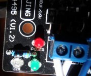
Power LED faintly flickers.
Blue LED USB lights comes on when USB plugged in but goes out.
When using Coax or Optic the Green LED goes out, my DAC operates with no LEDs on (?!)
Would the erratic behavior of the LEDs indicate a flaw with my board?
Thanks! Mack
Thanks Chris. I'll have to read the entire thread.
After a couple hours of casual listening I noticed:
-some vocals seem exaggerated and forward.
-bass seems less powerful using Coax and Optical than USB.
Power LED faintly flickers.
Blue LED USB lights comes on when USB plugged in but goes out.
When using Coax or Optic the Green LED goes out, my DAC operates with no LEDs on (?!)
Would the erratic behavior of the LEDs indicate a flaw with my board?
Thanks! Mack
Too loud mids issue has been encountered by many diyers, solution is not obvious. It has been solved on my board but I,Ve made so many changes that I couldn't garantee with one is really relevant. Better to first check power supply.
About the Leds: hard to say if there's a issue or not unless being sure of what is expected, except for psu led which usually doesn't blink.
How do you power the board ?, what are the characteristics of the PSU or the transformer used ?
Do you have a DMM in order to do some basics checks.
Can you post close pictures (I can't open the one already published) of the board, mainly the parts in TO220 packages, and the riser board. On AliExpress picture we can't see the wm8805 and the PCM2706.
About the bass: do you use same source with same sampling frequency and same track and switch it's output on the 3 input of the DAC ? Otherwise it will be hard to confirm that the bass boost is coming from the DAC.
Another thread with some insights : Ebay USB DAC board
Chris
.......
Do you have a DMM in order to do some basics checks.
Can you post close pictures (I can't open the one already published) of the board, mainly the parts in TO220 packages, and the riser board. On AliExpress picture we can't see the wm8805 and the PCM2706.
About the bass: do you use same source with same sampling frequency and same track and switch it's output on the 3 input of the DAC ? Otherwise it will be hard to confirm that the bass boost is coming from the DAC.
Another thread with some insights : Ebay USB DAC board
Chris
Thank you Chris for replying. I checked the input with my digital volt meter. I use my same test songs to compare though the time it takes to switch DACs makes it difficult to be 100% sure. Later this week I'll do a test sweep.
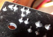
Here are some hastily taken photos, posted as I head off to work.
Thanks again, Mack
Thank you Chris for replying. I checked the input with my digital volt meter. I use my same test songs to compare though the time it takes to switch DACs makes it difficult to be 100% sure. Later this week I'll do a test sweep.
Here are some hastily taken photos, posted as I head off to work.
Thanks again, Mack
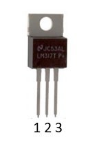
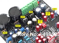
Based on your pictures and the ones from AliExpress we can identify some regulators : a 317 near the leds then two LT1085-3.3, a 7808 on heat sink. The Other one on heatsink will require a front picture. The two parts in TO220 package near the big capacitors are probably transistors used by the Darlington + zener stabilizer used to power the opamp. That's a lot! And a chip is missing: the wm8805 supposed to handle spdif inputs. Is there underneath the board ?
Could you take picture or take note of what writen on the parts on heat sink and close the big caps ? Based on that it'll be possible to check the power supply of the dac with the DMM and maybe understand what is going on with power led.
The transformer is ok for this duty, wiring of the two 15V may be checked. With the DMM in VAC mesure voltage across the two external screws of the 3 terminal connector. You should have near 35V, if close to zero swap the two wires of one (only one) of the two winding: brown or yellow.
Chris
Chris, I took photos as best I could.
I checked the voltage and got 37.4, 10.8 and 10.8.
I was hoping to find I'd misswired but volts look ok.
Cheer, Mack
Chris, I took photos as best I could.
Cheer, Mack
Here's the info from the pics. I hope there's enough info. Thanks.
on the bottom of the board:
WM8805GEDS
07ABMDX
------------------
74HC157D
AB762 04
Un0:302 E
on heat sinks:
F
1206
IRF9610
SEC
831
????
------------------
LM317T
GK05P
CHN 53??
???
---------------------
L7
LINIEAR
T1085
T-3.3
?08124???
----------------
LM317T
GK05P ?
CHN 53??
??
-----------------------
L7
LINEAR
T1085
T-3.3
??08124??
DAC PSU
Hi Tilroh,
Thanks for the pictures, it allows a first guess. see picture attached.
The two IRF parts are Mosfets, not Darlington. As they close some trimpot, they're probably part of two linear regulator : plus and minus supply for the opamp.
In order the test the DAC PSU some DC measurement can be done:
With the negative probe of the DMM connected to the center contact of the 3 screw terminal:
Chris
Hi Tilroh,
Thanks for the pictures, it allows a first guess. see picture attached.
The two IRF parts are Mosfets, not Darlington. As they close some trimpot, they're probably part of two linear regulator : plus and minus supply for the opamp.
In order the test the DAC PSU some DC measurement can be done:
With the negative probe of the DMM connected to the center contact of the 3 screw terminal:
- measure pin 2 of each LM317
- measure pin 2 of each LT1085-3.3
- measure pin 3 of 7808
- measure pin 4 and pin 8 of the opamp
- measure pin 2 and pin 3 of each IRF
Chris
Attachments
Hi Chris,
I put masking tape on a hat pin and managed to check the voltages without any causing any funny smells or smoke.
IRF610
pin 2
-1
pin 3
-11.81
IRF9610
pin 2
1
pin 3
11.84
LM317
-6.94
7808 pin 3
-7.92
Lt1085
-3.25
Lt1085
-3.29
LM317
-4.93
opamp
pin 4
11.83
pin 8
-11.85
Thank you,
Mack
I put masking tape on a hat pin and managed to check the voltages without any causing any funny smells or smoke.
IRF610
pin 2
-1
pin 3
-11.81
IRF9610
pin 2
1
pin 3
11.84
LM317
-6.94
7808 pin 3
-7.92
Lt1085
-3.25
Lt1085
-3.29
LM317
-4.93
opamp
pin 4
11.83
pin 8
-11.85
Thank you,
Mack
Hello Mack,
Good idea to protect the pin with tape!
Voltage are reversed, so were your probes but it’s not important") . Voltages seems ok, there’s no obvious issue, even if the purpose of two supply (8 and 5V) isn't clear. Voltage on pin 2 of the two IRF is odd, probably a measurement issue.
. Voltages seems ok, there’s no obvious issue, even if the purpose of two supply (8 and 5V) isn't clear. Voltage on pin 2 of the two IRF is odd, probably a measurement issue.
To summarize, following assumptions are reasonable:
the two IRF provide +/- 12V for the Opamp.
the two LT provide +3.3V for digital supply of 4495, 8805 and HC157.
the 317 running at 6.94V provide 4495 output stage supply, using a 317 at this position could be discussed.
Those 3 first supply should be enough to operate the DAC, but there are two others:
What usage for second 317 at 5V?, provide power to the USB board ?,it has an onboard 3.3V as required by PCM2706 even if usually 2706 is powered by the USB I/F.
What usage for the 7808? pre regulator for the two LT ?
To identify the cause of the power led blinking it could be interesting to identify where the led is connected. Usually, one pin of the led is be connected to a resistor, the other pin to ground or to one of the supply and the other pin of the resistor connected to ground or one of the supply. Ohmmeter is useful for this. In addition of the output of the various parts (pin 2 of 317, 1085 and pin 3 of 7808, IRF) their inputs should also be tested : (pin 1 of 317, 1085, 7808 and the pins of the two very large caps).
One last check is feasible: to measure voltage in DC then in AC after the two rectifier connected to the two 9V windings. This can be measured on the two big cap (not the biggest ones) near the 2 1085 and the 317.
If nothing goes out those tests, it’ll be difficult to investigate further on this blinking issue without a oscilloscope, but visual inspection and resoldering of all parts involved in the supply will be recommended.
For the sound quality issue, if you still encounter it, there’re some tricks which worth a trial, mainly around the +7V 4495 supply (the 317 running at 6.94V) and Opamp decoupling.
Chris
Good idea to protect the pin with tape!
Voltage are reversed, so were your probes but it’s not important
. Voltages seems ok, there’s no obvious issue, even if the purpose of two supply (8 and 5V) isn't clear. Voltage on pin 2 of the two IRF is odd, probably a measurement issue.To summarize, following assumptions are reasonable:
the two IRF provide +/- 12V for the Opamp.
the two LT provide +3.3V for digital supply of 4495, 8805 and HC157.
the 317 running at 6.94V provide 4495 output stage supply, using a 317 at this position could be discussed.
Those 3 first supply should be enough to operate the DAC, but there are two others:
What usage for second 317 at 5V?, provide power to the USB board ?,it has an onboard 3.3V as required by PCM2706 even if usually 2706 is powered by the USB I/F.
What usage for the 7808? pre regulator for the two LT ?
To identify the cause of the power led blinking it could be interesting to identify where the led is connected. Usually, one pin of the led is be connected to a resistor, the other pin to ground or to one of the supply and the other pin of the resistor connected to ground or one of the supply. Ohmmeter is useful for this. In addition of the output of the various parts (pin 2 of 317, 1085 and pin 3 of 7808, IRF) their inputs should also be tested : (pin 1 of 317, 1085, 7808 and the pins of the two very large caps).
One last check is feasible: to measure voltage in DC then in AC after the two rectifier connected to the two 9V windings. This can be measured on the two big cap (not the biggest ones) near the 2 1085 and the 317.
If nothing goes out those tests, it’ll be difficult to investigate further on this blinking issue without a oscilloscope, but visual inspection and resoldering of all parts involved in the supply will be recommended.
For the sound quality issue, if you still encounter it, there’re some tricks which worth a trial, mainly around the +7V 4495 supply (the 317 running at 6.94V) and Opamp decoupling.
Chris
thanks Chris, I'll have a look on the bottom of the board and try and trace the red power led.
Last night I played the DAC using Coax and Optic. Both gave a loud tearing crackle when Play was first pressed in FooBar2000. Selecting Stop and Play worked fine after the first Play. I was using a XMOS USB to Coax/Optic converter as usual. Both amps and active XO were on before pressing Play. Other DACs have a little pop but this was much louder. My wife ask if everything was OK from the next room.
USB input is normal.
Cheers, Mack
..........but visual inspection and resoldering of all parts involved in the supply will be recommended.
........
Chris
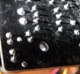
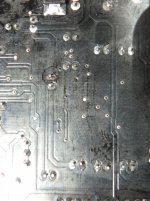
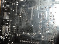
I took some photos of the LEDs and underneath of the board. Nothing stood out to me.
An externally hosted image should be here but it was not working when we last tested it.
I took some photos of the LEDs and underneath of the board. Nothing stood out to me.
An externally hosted image should be here but it was not working when we last tested it.
Can't open link, tried on Ipad and two PC...
You can attach pictures with tha paper clip icon.
Chris
Can't open link, tried on Ipad and two PC...
Chris
Thanks for letting me know. Here's the large pics
Attachments
Thanks for letting me know. Here's the large pics
Hi Tilroh
Solder joints looks very good, if they're all the same as the ones on the pictures, they're unlikely an issue cause.
The sound you hear at USB I/F startup (only startup) with Foobar is probably due to the implementation of the 8805 which deliver a clock to the 4495 only when it receive a clock form it's spdif input, which may be different with other 8805 implementation or other chip. In such condition the 4495 can produce a loud noise. To confirm you could try to reproduce the sound by removing / inserting the spdif (coax or toslink) input once foobar has started playing and is paused.
Chris
That explanation makes sense. the noise only happens when Play is first pushed. Afterwards pressing play/pause makes no sound. I'll try unplugging the spdif cables this weekend.
I use Foobar as a preamp so my amps are at full volume. The noise pressing Play the first time is scary even thou I only have 8 watts on the 4" Scan Speaks and 50 watts on the 8" Daytons.
Thank you for the insight Chris.
Cheers, Mack
I use Foobar as a preamp so my amps are at full volume. The noise pressing Play the first time is scary even thou I only have 8 watts on the 4" Scan Speaks and 50 watts on the 8" Daytons.
Thank you for the insight Chris.
Cheers, Mack
I experimented some this afternoon and found that removing replacing the coax cable didn't cause the crackling/sizzling noise, only selecting Play in Foobar the first time after the DAC is connected. Afterwards selecting Play, Stop, Next have no bad effects. USB is fine. Looks like it's a design problem.
- Status
- This old topic is closed. If you want to reopen this topic, contact a moderator using the "Report Post" button.
- Home
- Source & Line
- Digital Line Level
- What do these DIP switches do?