Hello!
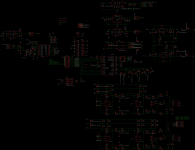
I'm trying to build a DAC using the PCM1792A chip. I have the first revision working, and I'm using OPA1632 for the I/V stage. I basically copied Twisted Pear's IVY design but with SMT components (this project is for personal usage only and will be released as open-source for anyone interested in this work).
Everything works and sounds good as far as I can tell (haven't had a chance to measure it - couldn't get RMAA to work on my Vmware since I'm using a Mac). I tried looking for oscillations using a 100MHz Rigol scope but couldn't see anything obvious. All opamps get hot enough that touching them for more than a few seconds is not possible. I tried adding cheap 1nF ceramic capacitors in parallel with the feedback resistors R1/R2/R17/R18 but there was no noticeable difference in temperature. They also get hot even without anything coming out of the DAC.
Any idea where to go from here? Is it possible that an SO-08 package was just a poor choice?
Thanks <3
Attachments
Last edited:
They also get hot even without anything coming out of the DAC.
These are 180MHz parts, so oscillation is a real possibility.
Did you follow the power supply/layout guidelines, and also use 10nF bypasses?
I would build a pcb with only the voltage supplies and one op amp, and troubleshoot from there.
Last edited:
The OPA1632 does run hot. You can calculate its idle power dissipation P = I * V, where I is the quiescent current and V is the rail-rail supply voltage.
If you're running +-15V rails, consider reducing it to +-12V or even +-10V, and it will still have enough output voltage swing for line out purposes, and it will run much cooler.
If you're running +-15V rails, consider reducing it to +-12V or even +-10V, and it will still have enough output voltage swing for line out purposes, and it will run much cooler.
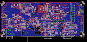
I do use 10nF bypass capacitors, but my layout is not a 1:1 match to their recommended layout.
I am running it at +-12v and I believe the quiescent current is 14mA. That gives 336mW of heat. Is that enough to make something too hot to touch for more than a few seconds?
Thanks again!
I am running it at +-12v and I believe the quiescent current is 14mA. That gives 336mW of heat. Is that enough to make something too hot to touch for more than a few seconds?
Thanks again!
If you are willing to sacrifice an OPA1632, then lift the Vcc and Vee pins, insert 1 ohm resistors in series with the power supply + and - rails, and measure the current consumption. Cross-reference your readings with the manufacturer specifications. Once measured okay, replace the OPA1632.
Borrow an oscilloscope from someone, if you can, and check for oscillations at the OPA1632 outputs. If you can't borrow, just measure the current consumption like I suggested in the first paragraph. Oscillations at the OPA's output would increase the current consumption considerably.
As other suggested, OPA1632 does run hot; however, at least in my opinion, you may have a problem of some sort if you can't rest your finger indefinitely on the OPA1632 SOIC8 package... Measurements that look okay (above), would hopefully prove that I'm wrong, in which case that particular OP in SOIC8 does indeed run very hot.
Suggestion: start using an LT3045 for all your positive power supply rails. For negative, use a TPS7A3301. Also, that 11.288Mhz oscillator should (must) be of a very low phase noise type.
Good luck,
Nick
I am running it at +-12v and I believe the quiescent current is 14mA. That gives 336mW of heat. Is that enough to make something too hot to touch for more than a few seconds?
It would help if the IC bottom is soldered to the pcb for heat sinking.
Extreme_Boky - that's an interesting idea. I might try that over the weekend if I get a chance. I am not sure my SMT soldering skills are good enough to be able to lift the legs without creating a mess/tearing the pad.
I have a Rigol 100MHz scope here but I failed seeing anything suspicious on the outputs. How would these oscillations look like if they were happening? What kind of voltage swings can I expect? Perhaps I am doing something wrong with how I'm trying to measure?
Thanks for the regulator recommendations. I'll keep that in mind for the next project, or perhaps a different revision of this one. The 12.288MHz isn't currently installed, but the one I ordered is this one: http://www.mouser.com/Search/Produc...8virtualkey54920000virtualkey549-C3391-12.288
Datasheet claims "providing very low Jitter and Phase Noise. No Sub-Harmonics are present in the Output Signal.". Assuming I do end up using it, would it be adequate?
rayma - The SO08 packaging does not have that... they have a different version that does, and perhaps I made a mistake not using it.
Thanks for taking the time to look into this!
The best commercial oscillator is an NZ2520SDA. However, you will struggle to get it - try writing to NDK and see what they are going to say. An alternative is an NZ2520SD which is readily available. See if you can figure out how to isolate that oscillator from the vibrations and from the influence of temp. changes...
The best way to check for oscillations is to play a sweep, either log or lin. I am pretty sure you'll be able to download a "BinkAudioTestCD" from the internet if you search a bit... and then play the tracks from that CD while monitoring the output with the scope. Check for the overshoots and ringing that, if you do have a problem, will be superimposed on "top" of the playing signal.
One way to kill oscillations is to insert around 10-ohm resistor in series with the OP's output.
I just realised that your OP is not soldered to the PCB ground, which could explain the high running temp... so you may not have the oscillation problems after all. As I mentioned already, to be sure, insert a resistor in each supply line and then measure the voltage drops.
Nick
Last edited:
Thanks for the oscillator recommendations!
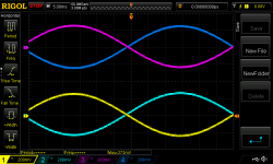
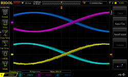
I got the Bink test CD and made some measurements. It looks mostly clean, but I did manage to catch something weird on one of the channels. The blue/purple are +/- of one channel, and the cyan/yellow are the +/- of the other channel.
Are these tiny spikes on the yellow channel the mess I am looking for?
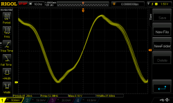
Unrelated, but my MCK signal looks terrible anything I can/should do about that?
I got the Bink test CD and made some measurements. It looks mostly clean, but I did manage to catch something weird on one of the channels. The blue/purple are +/- of one channel, and the cyan/yellow are the +/- of the other channel.
Are these tiny spikes on the yellow channel the mess I am looking for?
Unrelated, but my MCK signal looks terrible
anything I can/should do about that?Attachments
In the I/V stages, OPA1632's Vocm pins looks problematic.The Vocm pin set *output* common voltage.+- input pins are virtual-shorted each other, but not to Vocm.PCM1792A output "sources" (↔sink) 6.2mA at digital silence.So OPA1632's +- input pins potential will be 0V+750Ω*6.2mA=4.65V which exceeds PCM1792A's limitation, or even its supply voltage, it must be clamp protected somehow.
I don't know where your waveform probed, but I can't see why, how your DAC runs in such a condition.The solution is to set Vocm pin -4.65V or sink common 6.2mA with CCS.
I don't know where your waveform probed, but I can't see why, how your DAC runs in such a condition.The solution is to set Vocm pin -4.65V or sink common 6.2mA with CCS.
Unrelated, but my MCK signal looks terrible
I don't suppose that by any chance your oscilloscope's probe is set to x1?
In the I/V stages, OPA1632's Vocm pins looks problematic.The Vocm pin set *output* common voltage.+- input pins are virtual-shorted each other, but not to Vocm.PCM1792A output "sources" (↔sink) 6.2mA at digital silence.So OPA1632's +- input pins potential will be 0V+750Ω*6.2mA=4.65V which exceeds PCM1792A's limitation, or even its supply voltage, it must be clamp protected somehow.
I don't know where your waveform probed, but I can't see why, how your DAC runs in such a condition.The solution is to set Vocm pin -4.65V or sink common 6.2mA with CCS.
Why do you think it exceeds it's limitation? It's analog supply voltage is +5V. Waveforms were probed on the PL connectors - so at the end of the signal chain.
I don't suppose that by any chance your oscilloscope's probe is set to x1?
Hm, good call. Pretty sure it was set to x1. I'll try again with x10. Thank you!
Edit: Looks a bit cleaner with x10 but still not a nice square wave
Last edited:
Why do you think it exceeds it's limitation? It's analog supply voltage is +5V. Waveforms were probed on the PL connectors - so at the end of the signal chain.
Oh, I remembered the supply is 3.3V.Then it is inside of rail voltage.Although that, I recommend the node voltage to be 0V or so as nominal condition in the datasheet. When the node voltage is 4.65V , internal "current segments" (CCSs and switches) comprised of Pch MOSFETs are running low Vds and may affect switching characteristics - it may be the cause of the glitches in your waveforms.
I found similar discussions in this thread.http://www.diyaudio.com/forums/digi...rential-voltage-line-level-pcm1794-et-al.html
Don't expect a nice looking square wave if you're measuring tens of MHz with a regular scope's test probe. The ground lead has enough inductance to make the waveform ugly. Read up on RF measurements...
Didn't think 12MHz would be fast enough for that effect... I'll google and read about that. Thanks
Oh, I remembered the supply is 3.3V.Then it is inside of rail voltage.Although that, I recommend the node voltage to be 0V or so as nominal condition in the datasheet. When the node voltage is 4.65V , internal "current segments" (CCSs and switches) comprised of Pch MOSFETs are running low Vds and may affect switching characteristics - it may be the cause of the glitches in your waveforms.
I found similar discussions in this thread.http://www.diyaudio.com/forums/digi...rential-voltage-line-level-pcm1794-et-al.html
I'll take a look at that thread. Thank you!
Shinja - thanks again for pointing out the Vocm issue and the other thread. While I am not sure it contributes anything to the heat issue, it's definitely a problem in the design. I'm wondering where to go from here. I could create a -4.65V reference on Vocm but to my understanding this will result in DC offset I'll need to remove with capacitors. Is that correct?
Would using a CCS be better (and not result in DC offset)?
Would using a CCS be better (and not result in DC offset)?
- Status
- This old topic is closed. If you want to reopen this topic, contact a moderator using the "Report Post" button.
- Home
- Source & Line
- Digital Line Level
- OPA1632Ds getting super hot in a PCM1792A DAC I'm building