I'll have a look at increasing the damping of the filter - that way you'll get the benefit of the rejection of images at higher frequencies but not have the rising HF response needed for NOS eq. I think its going to be simply tweaking a resistor value....
Attached the revised schematic - I took it that you'd settle on 100R for the I/V resistor and adjusted the other values accordingly. It looks impressively flat now")
Howdy Abraxalito... If you don't mind, what would the values be for this circuit but only four tda1387x4 chips? Targeting 2V RMS output.
Thanks!
Hi Matt - 2VRMS output isn't going to be achievable coming directly from the DAC chips themselves. This is because the output compliance spec for the DAC (0 to 3.5V) is narrower than what's needed to fit 2VRMS (5.6V). If you increase the TDA1387 supply voltage to 6V you can almost get there - you'll get about 1.6VRMS.
Hi Matt - 2VRMS output isn't going to be achievable coming directly from the DAC chips themselves. This is because the output compliance spec for the DAC (0 to 3.5V) is narrower than what's needed to fit 2VRMS (5.6V). If you increase the TDA1387 supply voltage to 6V you can almost get there - you'll get about 1.6VRMS.
I see. I guess what I meant was, for 4x tda1387, what iv resistor value to get the maximum output without any clipping? In other words, how to not put an artificial ceiling on the output?
Also: is the iv resistor value the same whether doing passive iv or using an op-amp?
The tda1387 datasheet shows a 2.7k iv resistor - but that's across an opamp. Is that value the same when using passive iv? Ultimately, what I'm getting at: can we generalize the iv resistor value to be something like this: R = 2.7k / X, where X=number of tda1387 chips. (Although 100R is lower than the 337.5R implied by my formula for 8 chips, the discussion above suggests it sounds better with a lower value.)
Lastly - in that circuit you drew (assuming 8 chips / 100R iv resistor) - you said if the iv resistor changes, a cap has to change with it to maintain the same ratio. It wasn't clear to me which cap it was. That's really what I'm getting at - I would assume for 4 chips instead of 8, the iv should be doubled to 200R. But I wasn't sure which cap to half or double as well.
I see. I guess what I meant was, for 4x tda1387, what iv resistor value to get the maximum output without any clipping? In other words, how to not put an artificial ceiling on the output?
Ah, right, I see now. I was playing with one of Lee's simpler DACs (4 * TDA1387) and looking on my scope. I noticed that the DAC's output did go beyond the datasheet maximum compliance (3.5V for a 5V supply) by at least half a volt, maybe more. But I don't have a distortion analyser to check if that extra swing was subject to distortion. He's using 1k on that DAC, which according to the DS is too high. But in practice it looks fine on the scope.
Also: is the iv resistor value the same whether doing passive iv or using an op-amp?
Yes - given the same output voltage we need the same resistor value no matter the 'style' of I/V. Opamp I/V though isn't subject to the compliance limitations of the DAC so you can get much higher output if you want, limited only by the opamp supply rails.
The tda1387 datasheet shows a 2.7k iv resistor - but that's across an opamp. Is that value the same when using passive iv?
Yep. I would guess its chosen to give 1VRMS output (2.8V p-p).
Ultimately, what I'm getting at: can we generalize the iv resistor value to be something like this: R = 2.7k / X, where X=number of tda1387 chips.
Yes, I would suggest R=3.9k based on experience or R=3.3k if you want to go strictly by the datasheet - being very conservative.
(Although 100R is lower than the 337.5R implied by my formula for 8 chips, the discussion above suggests it sounds better with a lower value.)
I've forgotten whether 100R is my modified value or was the original. I need to go back and check. It could be that this lower value is called for by the filter. In the absence of any filter I can't think of a reason to choose a lower value than our new formula suggests.
Lastly - in that circuit you drew (assuming 8 chips / 100R iv resistor) - you said if the iv resistor changes, a cap has to change with it to maintain the same ratio. It wasn't clear to me which cap it was. That's really what I'm getting at - I would assume for 4 chips instead of 8, the iv should be doubled to 200R. But I wasn't sure which cap to half or double as well.
I'll go back to find the original circuit and have a play to see if the filter can still work with twice the output impedance from the DAC. I assume you wanted the 'flat' form of the filter - for 2X OS or higher?
200R I/V resistor...
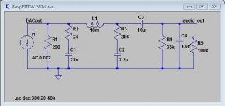
Turns out that with 200R for the I/V I can't get the response I want - it requires changing the inductor to 22mH. The nearest fit with L=10mH is with a roll-off at a higher frequency (30-40kHz). Here's what I've got . If you stick with 100R you'll get a nicer response but your output level will be rather low. You could of course solder an extra 4 chips on top of the 4 you have....
Turns out that with 200R for the I/V I can't get the response I want - it requires changing the inductor to 22mH. The nearest fit with L=10mH is with a roll-off at a higher frequency (30-40kHz). Here's what I've got . If you stick with 100R you'll get a nicer response but your output level will be rather low. You could of course solder an extra 4 chips on top of the 4 you have....
Attachments
Last edited:
Turns out that with 200R for the I/V I can't get the response I want - it requires changing the inductor to 22mH. The nearest fit with L=10mH is with a roll-off at a higher frequency (30-40kHz). Here's what I've got . If you stick with 100R you'll get a nicer response but your output level will be rather low. You could of course solder an extra 4 chips on top of the 4 you have....
Hi Abraxalito,
can you share which inductor brand/ model that you use for the above mod? i found one inductor : FSR1013-223KL Bourns | Mouser
would that works?
thanks
The Bourns one you linked will certainly work but its just a bit high DCR which leads to slightly droopy high frequencies. This Taiyo Yuden one looks better (about half the DCR) but they're not saying whether its shielded or not. From the picture it does look shielded : LHL10TB223J Taiyo Yuden | Mouser 香港
The Taio Yuden one is not shielded
I found this inductor (Ferrite core) 07MFG-223J-50 Fastron | Mouser
22mH, 19.5ohm DCR Qfactor 100. max DC current is only 25 ma....
Not sure if the ferrite core will matter or not, but I am more concern on max DC current..
daniel-
I found this inductor (Ferrite core) 07MFG-223J-50 Fastron | Mouser
22mH, 19.5ohm DCR Qfactor 100. max DC current is only 25 ma....
Not sure if the ferrite core will matter or not, but I am more concern on max DC current..
daniel-
Would it be possible to draw up a schematic of the output section? I can't follow along well enough from the textual description to picture what's going on. For example 'RC' means R and C in series or in parallel?
<later> Added schematic - do I have it correct?
Hi Abraxalito, I'm experiencing that a damped (or snubber) capacitor at the output of a current DAC sounds better than just using the cap.
Which is a directionally correct formula for the R value given the capacitance I want to use? I saw values between few ohms to 100ohm.
(I'm just talking regarding a IV passive prefilter, as a first analog stage to shunt RF energy to ground, so the cap is around 1nF).
- Status
- This old topic is closed. If you want to reopen this topic, contact a moderator using the "Report Post" button.
- Home
- Source & Line
- Digital Line Level
- Improving passive I/V for Pi dac 8 x TDA1387