Hello Lemon,
There's something strange with my DIyAudio thread list : I've received a mail notification of your last post , copied here :
"Cris, Potato Semi is.
I done a quickly test, after the correction of RC (100R, 100p).
I see that is worse now, the FFT unlock occurs more frequently and delays a lot to stabilized.
I have attached two captures, a bclk PO74G74A input and after the PO74G74A (output), with the modification of RC.
I see a delay (second pulse at the same time) of 10 ns, if you see at the video of post#2 this delay was 20ns."
But I do not see it in the thread list, last post in DimDIm #40 and previous is mine yesterday evening #39. Am I the only one not seeing your post ?
I'm a little behind on my part of the testing, but I did take a closer look at this "delay" of the BCLK coming out of our flip-flops.
It turns out that it is not a delay - it's just that some of the pulses have different period than others. This manifests itself like the "delayed" signal seen in lemon's screengrab.
Look at these two videos:
https://www.youtube.com/watch?v=nVRuWlQ5chY
https://youtu.be/YGXnZuIOqVE
Both of them are of the BCLK after its flip flop. The first one is of a 44.1K SR, the second one of 192K SR.
Notice how things change as I move the wave on the x and y axis.
I believe that this issue must be investigated and sorted out first.
Also, look at this capture of the I2S signal both before (channels 0, 1, 2) and after the flip flops (channels 4, 5, 6). Ignore channel 3, it was supposed to be the MCLK but my logic analyzer has nowhere near the required bandwidth to capture it properly:
https://ibb.co/j2u7oQ
This was done on an unpopulated dual ak4490 board, with just the flip flops for one channel soldered on. Signal source was an Amanero, MCLK was the Amanero's.
It seems that the signal is OK in that the LRCK does start at the falling edge of BCLK.
Also the reclocking seems to be helping the DATA signal.
In this case, the BCLK looks OK on the oscilloscope. No "ghosting" or anything.
But, what you are looking at is the beginning of the capture. After a few seconds things might be different - I didn't think to capture several seconds af data and scroll down a few seconds to see what happens. That is on my to-do list.
Yes, I definitely agree, this is not a delay (see post #28).
I miss time to carefully read your post, It should be allright tonight.
About the 44.1kHz video :
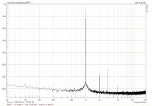
It looks like the period (T) of the signal is constant and is close to 360nS which is consistent with expected value for BICK : 44.1KHz*32*2 bits/frame = 2.8224 Mb/s; bit period =1/2.8224M = 354nS.
As said, sometime BICK high level duration is T/2 which is expected behavior, and sometime high level duration th=T/2 + 20ns close to 380nS while tlow=T/2 - 20nS. This 20nS value is clearly measurable on the 192KHz video.
Assuming you run at 8x oversampling, MCLK is 8*2.8224 Mb/s = 22.5792 MHz; period = 44.28nS.
It looks like sometime, on rising edge of MCLK the D flipflop latch a zero and sometime it latch a 1. This may occurs when D input and CK input change at the very same time without having a setup time on D before clock rise. But this is weird because in that case we should have a variation of th equal to the period of the clock (44.28nS) and we’ve got half !. Maybe what we see on scope is not what really happen and it’s a syncing issue, a faster protocol analyzer would be helpful…
But, to be sure, could you confirm frequency of MCLK ?
If I may, some interesting measures with scope could be the following :
It's not easy to figure what can go wrong without been able to make some tests ! I still think it’s a clocking issue related to lack of compliance with datasheet (Page 20 note 21) and respect of tSDS and tSDH. If you look at I2S timing on page 33 (mode 3 timing) you’ll see LRCK changing on falling edge of MLCK and Data sampled on rising edge (see text in previous page). You can get close to this by trying to invert MCLK of the BICK D latch only.
Sorry for being verbose, I’m currently working on an AKM DAC project (without reclocking !) and I still haven’t been working on this side of the chip…simply because I’m using a 4118 which handle this stuff very well.
Chris
It looks like the period (T) of the signal is constant and is close to 360nS which is consistent with expected value for BICK : 44.1KHz*32*2 bits/frame = 2.8224 Mb/s; bit period =1/2.8224M = 354nS.
As said, sometime BICK high level duration is T/2 which is expected behavior, and sometime high level duration th=T/2 + 20ns close to 380nS while tlow=T/2 - 20nS. This 20nS value is clearly measurable on the 192KHz video.
Assuming you run at 8x oversampling, MCLK is 8*2.8224 Mb/s = 22.5792 MHz; period = 44.28nS.
It looks like sometime, on rising edge of MCLK the D flipflop latch a zero and sometime it latch a 1. This may occurs when D input and CK input change at the very same time without having a setup time on D before clock rise. But this is weird because in that case we should have a variation of th equal to the period of the clock (44.28nS) and we’ve got half !. Maybe what we see on scope is not what really happen and it’s a syncing issue, a faster protocol analyzer would be helpful…
But, to be sure, could you confirm frequency of MCLK ?
If I may, some interesting measures with scope could be the following :
- A channel : BICK at input of the D , B channel : BICK at output of the D, Sync: rising edge of A then falling edge in order to cross check. That should allow to understand how D input is reproduced on output, the additional duration of high should be visible
- If you have a C channel add MCLK, if not : A channel : BICK at input of the D, B channel : MCLK, Sync rising edge of A. 8 clock period of MCLK should be visible per BICK period, we should look at when rising edges of MCLK occurs around BICK changes, this should allow to understand why we have variation of high level time (th).
It's not easy to figure what can go wrong without been able to make some tests ! I still think it’s a clocking issue related to lack of compliance with datasheet (Page 20 note 21) and respect of tSDS and tSDH. If you look at I2S timing on page 33 (mode 3 timing) you’ll see LRCK changing on falling edge of MLCK and Data sampled on rising edge (see text in previous page). You can get close to this by trying to invert MCLK of the BICK D latch only.
Sorry for being verbose, I’m currently working on an AKM DAC project (without reclocking !) and I still haven’t been working on this side of the chip…simply because I’m using a 4118 which handle this stuff very well.
Chris
Last edited:
Chris, thank you very much for your time.
I'll take the measurements that you described tomorrow (with a clear head). My oscilloscope is a 4 channel one so I can add the MCLK.
By the way, in my 44.1K video the MCLK is at 45.1584 MHz so that explains the ~20ns period. In the 192K video MCLK is at 49.152 MHz, in both cases generated by my Si570.
Will we get to see your AKM DAC project when it's finished?
I seem to have made some progress.
I desoldered the Si570 from the board and provided MCLK from my Amanero (22/24MHz clocks).
The "ghosting" of the BCLK went away, proving that it was indeed an "artifact" of the different clock domains between the DAC board and the I2S source board.
Also, the "unlocks" went away as well, at all sampling rates and frequencies.
However, I am still a little worried about the timing between the BCLK and the LRCK.
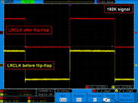
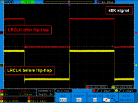
Looking at these grabs, Input 4 (first trace from the top) is BCLK before the flip-flop, Input 2 (second trace from the top) is BCLK after the flip-flop, Input 3 (third trace from the top) is LRCK before the flip-flop, Input 1 (last trace from the top) is BCLK after the flip-flop.
44.1KHz:

88.2KHz:

172.4KHz:
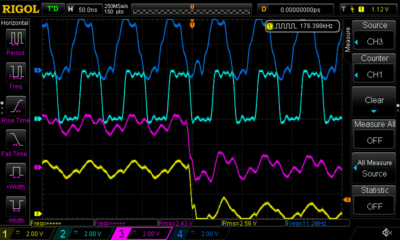
192KHz:
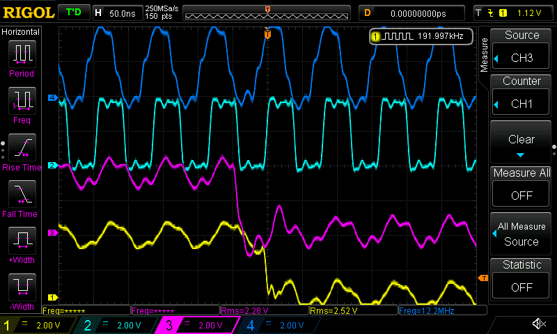
It looks to me like at some frequencies the LRCK after the flip flops is delayed a little too much, especially in case of the 192K SR. It looks like it's almost gotten to the leading edge of BCLK, which should be a problem. However, the DAC does not seem to mind.
Don't pay too much attention to how clean the traces look - grounding was a mess while I was doing my tests.
One last thing, with the Amanero's MCLKs I couldn't get the flip-flops to do their work for 352K+ SRs but that is to be expected.. I'll also do tests with other I2S sources, ones that have faster MCLKs.
Your thoughts?
I desoldered the Si570 from the board and provided MCLK from my Amanero (22/24MHz clocks).
The "ghosting" of the BCLK went away, proving that it was indeed an "artifact" of the different clock domains between the DAC board and the I2S source board.
Also, the "unlocks" went away as well, at all sampling rates and frequencies.
However, I am still a little worried about the timing between the BCLK and the LRCK.
Looking at these grabs, Input 4 (first trace from the top) is BCLK before the flip-flop, Input 2 (second trace from the top) is BCLK after the flip-flop, Input 3 (third trace from the top) is LRCK before the flip-flop, Input 1 (last trace from the top) is BCLK after the flip-flop.
44.1KHz:
88.2KHz:
172.4KHz:
192KHz:
It looks to me like at some frequencies the LRCK after the flip flops is delayed a little too much, especially in case of the 192K SR. It looks like it's almost gotten to the leading edge of BCLK, which should be a problem. However, the DAC does not seem to mind.
Don't pay too much attention to how clean the traces look - grounding was a mess while I was doing my tests.
One last thing, with the Amanero's MCLKs I couldn't get the flip-flops to do their work for 352K+ SRs but that is to be expected.. I'll also do tests with other I2S sources, ones that have faster MCLKs.
Your thoughts?
Attachments
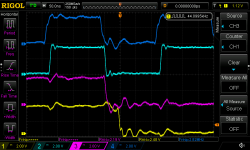
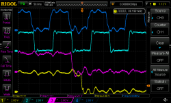


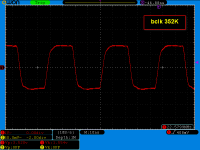
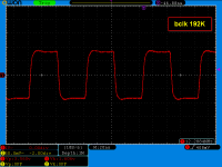
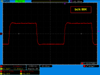
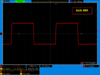
Just, I tried the same method like Dimitris.
I feed with amanero mclk the AK board and the rest of i2s signal are coming from the Acko S03 board normally.
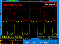
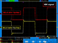
All the "unlocks" went away as well, at all sampling rates and frequencies like Dimitris but I have no any lucky with the "ghosting" of the BCLK pulse that remains with a random "ghosting" delay of 20-22ns depends from the music sampling.
I have included 48/192K captures for this purpose.
I repeat the same for the LRCLK, with capture before and after flip-flop but I don't see the same delay as Dimitris. I have included 48/192K captures for this purpose.
At 352/384K sampling files, the "ghosting" pulse (bclk) is major and at random times covers 2 or 3 pulses with opposite phase or same phase (it is very complicated to captured in photo, only with a video). This is the reason that we can't to reproduce these sampling music files with the reclocking flip-flops.
I feed with amanero mclk the AK board and the rest of i2s signal are coming from the Acko S03 board normally.
All the "unlocks" went away as well, at all sampling rates and frequencies like Dimitris but I have no any lucky with the "ghosting" of the BCLK pulse that remains with a random "ghosting" delay of 20-22ns depends from the music sampling.
I have included 48/192K captures for this purpose.
I repeat the same for the LRCLK, with capture before and after flip-flop but I don't see the same delay as Dimitris. I have included 48/192K captures for this purpose.
At 352/384K sampling files, the "ghosting" pulse (bclk) is major and at random times covers 2 or 3 pulses with opposite phase or same phase (it is very complicated to captured in photo, only with a video). This is the reason that we can't to reproduce these sampling music files with the reclocking flip-flops.
Attachments
We have a good news.
As the problems occur due to double clock domains, we tried to flash at slave mode the amanero board.
Now the two external clocks of Acko S03 board drive the mclk signal into the Xilinx CPLD of Amanero and all system has one clock domain.
The same can be applied by Si570, also.
With this setup there is no any FFT signal unlocking and all the sampling files from 44.1-384KHz play well.
The BCLK "ghosting" delay pulse has gone, also.
Summary, with the Amanero slave mode all the problems resolved and the Flip-Flop technique works fine.
Thanks to all for the encourage.
Attachments


Yesterday I re-soldered the Si570 to the DAC board, set up my Amanero for external MCLK (a.k.a. "slave") and did some tests. Everything seems to be working fine. ")
The only problem is that due to the Amanero's requirements I have to run the 4490s at 22/24MHz MCLK while I believe that it's preferable to be running them at their highest supported MCLK.
Meanwhile, the 22/24MHz clock has another drawback: It's not fast enough to do reclocking on 352/384K signals (but it might work if we were to invert it). So in any case, very high SRs are a problem.
Acko's reclocker with its 45/49MHz clocks is OK with the higher SRs but the 4490s are essentially overclocked with 44/49MHz MCLK when fed with low SRs (44.1-96KHz).
However, they seem to be working fine (and measure fine) even at these unsupported MCLKs.
So, for the time being I'll be running at 22/24MHz.
Now, on to properly setting up my AK4118 / AK4137 board.
Attachments
Dimdim,
Glad the problem is resolved.
Does the AKM DAC require any external analog out stages like the IV stages for ESS DACs?
Do you plan on a mutichannel DAC?
Does AKM offer enough datasheets and application notes including PCB guidelines to build a competent MC DAC?
How about these for ES9038
Glad the problem is resolved.
Does the AKM DAC require any external analog out stages like the IV stages for ESS DACs?
Do you plan on a mutichannel DAC?
Does AKM offer enough datasheets and application notes including PCB guidelines to build a competent MC DAC?
How about these for ES9038
AK dacs are voltage out so you don't need an I to V stage but you do need filtering, some amplification (if you insist on 2V RMS output) and a way to get rid of the DC that is present on the outputs.
Since the 4490 & 4497 are 2 channel DACs it would take a number of dac chips to do a multichannel design.. but it wouldn't be particularly difficult. AKM offers very good documentation, including reference design plans for some of their dacs (including the 4490). I'm not sure if they offer reference designs for their multichannel dac chips, I haven't checked. They are lower performance chips compared to the 4490/4497 chips.
But if I needed a multichannel dac I'd go for an ES9038 design.
I think it would be a little premature to be talking about a GB.. we're still testing and (just as important) listening to the DAC. In any case, this project will be fully opened to the public as soon as we consider it to be ready.
I've not considered doing a discreet balanced-out stage, but it's something that I am now considering, since I really like the sound of our discreet SE output stage.
However, I have almost finished designing an at-least-decent balanced-out design with op-amps.
An AK4497 design is not in my immediate plans. Perhaps some time next year.
AK dacs are voltage out so you don't need an I to V stage but you do need filtering, some amplification (if you insist on 2V RMS output) and a way to get rid of the DC that is present on the outputs.
Since the 4490 & 4497 are 2 channel DACs it would take a number of dac chips to do a multichannel design.. but it wouldn't be particularly difficult. AKM offers very good documentation, including reference design plans for some of their dacs (including the 4490). I'm not sure if they offer reference designs for their multichannel dac chips, I haven't checked. They are lower performance chips compared to the 4490/4497 chips.
But if I needed a multichannel dac I'd go for an ES9038 design.
Thanks Dimitris
Dimitris,
I like your dac
would you please explain If there Is a simple approach using digital receiver pcb and dac pcb - without arduino
what are controlling function of arduino:
- switch between PCM and DSD
- controlling clock freq
- controlling display
- controlling volume
- controlling digital filters
- else
can we use It In a simple way, without arduino with PCM only and spdif and usb Input
Last edited:
In order to run an AK4490 DAC without a controller you would need to set it up for parallel control. This means connecting certain pins to certain signals. My board has been set up only for serial control (Arduino etc.).
So the answer is no, my board only supports software control.
A different design (such as diyinhk's board) could be used without a controller, alas only for PCM signals (and only USB - otherwise you'd also need a s/pdif receiver chip and its support circuitry and/or controller).
So the answer is no, my board only supports software control.
A different design (such as diyinhk's board) could be used without a controller, alas only for PCM signals (and only USB - otherwise you'd also need a s/pdif receiver chip and its support circuitry and/or controller).
Quick update on our progress:
The project it going well, I've finished a beta version of the control code and everything seems to be working fine with I2S (via USB) input.
The SQ is simply excellent, either with our discreed output stage or with lemon's passive transformer stage. It is very detailed, yet not "clinical sounding", very dynamic, full bodied, and overall very engaging.
The SQ evaluation continues with more visits to friends' homes and sound systems.
On the to-do list is a redesign of the s/pdif inputs board, so as to make it a "slave" to the main DAC board's clock.
- Status
- This old topic is closed. If you want to reopen this topic, contact a moderator using the "Report Post" button.
- Home
- Source & Line
- Digital Line Level
- Arduino controlled dual mono AK4490 DAC