thank you so much guys! i understand dam1021 is still superior but 9028 is closing the gap. I was nearly decided to get one since it has everything in a board (spdif+i2s, reclocking, filters, balanced unbalanced and headphones output). i’d say it’s a very good dac for a first diyer, at a decent price. but then ian’s showing his modular approach with the 9028 and i’m wondering if i should wait for that, because it looks impressive as well.
Just to be clear, I have not yet listened to my BuffIIIPro builds. I was saying my DAM 1021 setups are currently my best. I suspect based on comments from others that will change once I get my BuffIIIPro setups running.
AND of course, implementation is everything. I have some additional mods planned to my DAM 1021 setups to give them the best chance of competing... and am pulling no punches on my BuffIIIPro builds for the same reasons.
Greg in Mississippi
noted, thank you so much
I've had the DAM for more than 2 years but it's still getting incremental upgrades. The Salas SSLV1.1 that powers it is about to be upgraded, its XMOS receiver too (with my design), plus Soren is close to giving out a new firmware that will support 4K taps for the FIR filter.
Hi again Dimitris,
Which are the essential differences between ArDAM1021 and ArDAM1021 Lite? I know display and memory usage are different, but anything else feature wise?
Thank you
ArDAM Lite "as is" only supports control via IR versus the rotary encoder support of the non-lite version. Other than that, just the obvious (aesthetic) differences.
noted, thank you! i'm trying to decide on a system, most likely will invest on a DAM1021 + your ArDAM (non-lite) and maybe an isolator. Do you sell your boards or offer the design somehow?
I'm out of pcbs at the moment, but I do have the full Eagle files for my Isolator PCB up on my blog: Universal Signal Isolator shield for the Arduino DUE | Dimdim's Blog
It's not hard to generate gerbers and order pcbs.
But I'm also considering starting a GB thread to see if there is interest.
It's not hard to generate gerbers and order pcbs.
But I'm also considering starting a GB thread to see if there is interest.
I'm out of pcbs at the moment, but I do have the full Eagle files for my Isolator PCB up on my blog: Universal Signal Isolator shield for the Arduino DUE | Dimdim's Blog
It's not hard to generate gerbers and order pcbs.
But I'm also considering starting a GB thread to see if there is interest.
great!
Hi Dear Dimitris;
Diyinhk ES9028 pro has gpio1 (40) Mute pin, i connect this pin led for listen some data(led on/off) but ı dont see anythings.
i listening native dsd with volumio, when i want forward music coming crankling sound, i want to make mute but i dont see anything gpio1 (40.pin)
How can activate gpio1 mute on your software?
My old es9018 mute out (40.pin) working so good, I need to activate my es9028pro automute register..
Your software is so silence when i forward dsd64 to dsd128, but when i forward same sample rate (dsd64 to dsd64) hearing crankling sound so high...
BR
Sercan...
Hi there Sercan,
Enabling automute on the 9028/38 is relatively easy to do. I've implemented it in the current version of my code, which I've not yet made public (since it includes a lot more functionality that has not been properly tested yet).
Let's see if this will work in your version of the code.
Change this:
into this:
This will not get your MUTE led to light (you need to add more code to do that), but if it works the way it should it will enable automute for you.
Enabling automute on the 9028/38 is relatively easy to do. I've implemented it in the current version of my code, which I've not yet made public (since it includes a lot more functionality that has not been properly tested yet).
Let's see if this will work in your version of the code.
Change this:
Code:
ChangeBit(dac, 0x00, 0, 1);                   // Put DAC in RESET mode
delay(500);                                   // Wait for 500ms
ChangeBit(dac, 0x00, 0, 0);                   // Take DAC out of RESET mode
mute = 1;                                     // Put DAC in mute
setMute();                                    // Put DAC in mute
ChangeBit(dac, 0x09, 7, 0);                   // Setup GPIO4
into this:
Code:
ChangeBit(dac, 0x00, 0, 1);                   // Put DAC in RESET mode
delay(500);                                   // Wait for 500ms
ChangeBit(dac, 0x00, 0, 0);                   // Take DAC out of RESET mode
mute = 1;                                     // Put DAC in mute
setMute();                                    // Put DAC in mute
ChangeBit(dac, 0x02, 7, 1);                   // Enable Automute
ChangeBit(dac, 0x02, 6, 1);                   // Enable Automute
WriteRegister(dac, 0x04, 255);                // Setup automute time to minimum (186ms for 44.1K FSR)
ChangeBit(dac, 0x09, 7, 0);                   // Setup GPIO4 for Automute / Lock Interrupt
This will not get your MUTE led to light (you need to add more code to do that), but if it works the way it should it will enable automute for you.
Hi Dear Dimitris;
I changed code like you say.
Your GPIO4 pin have 2 status ( Automute and Lock) now. This is problem for encoder and remote control. Because interrupt is HIGH, encoder and remote control can't work. How can i change GPIO4 pin info for only Lock status ?
I read ES9028PRO datasheet, and I changed again code like this :
Now mute led is working. But still GPIO4 interruptPin always be HIGH. Can you help me for that ?
I changed code like you say.
Your GPIO4 pin have 2 status ( Automute and Lock) now. This is problem for encoder and remote control. Because interrupt is HIGH, encoder and remote control can't work. How can i change GPIO4 pin info for only Lock status ?
I read ES9028PRO datasheet, and I changed again code like this :
Code:
  ChangeBit(dac, 0x02, 7, 1);                   // Enable Automute
  ChangeBit(dac, 0x02, 6, 1);                   // Enable Automute
  WriteRegister(dac, 0x04, 100);                // Setup automute time to minimum (186ms for 44.1K FSR)
  ChangeBit(dac, 0x08, 3, 0);                   // Setup GPIO1 for Automute
  ChangeBit(dac, 0x08, 2, 0);                   // Setup GPIO1
  ChangeBit(dac, 0x08, 1, 0);                   // Setup GPIO1
  ChangeBit(dac, 0x08, 0, 0);                   // Setup GPIO1

  ChangeBit(dac, 0x09, 7, 0);                   // Setup GPIO4
  ChangeBit(dac, 0x09, 6, 0);                   // Setup GPIO4
  ChangeBit(dac, 0x09, 5, 0);                   // Setup GPIO4
  ChangeBit(dac, 0x09, 4, 1);                   // Setup GPIO4 for Lock Interrupt
Now mute led is working. But still GPIO4 interruptPin always be HIGH. Can you help me for that ?
This should be working IIRC, so I'll need to actually test some things on my Buffalo to figure this out but my Buffalo is out of commission ATM. So I'm emailing you a beta version of my code that I believe will work for you. You will only need to add the GPIO1 stuff..
Edit: It looks like the current version of the code is actually in alpha.. not really compiling ATM.. so there is not much of a point in sending it to you. I'm sorry but it looks like you'll have to wait a while for me to sort things out.
Edit: It looks like the current version of the code is actually in alpha.. not really compiling ATM.. so there is not much of a point in sending it to you. I'm sorry but it looks like you'll have to wait a while for me to sort things out.
Last edited:
Hi Dear Dimitris;
I changed code like you say.
Your GPIO4 pin have 2 status ( Automute and Lock) now. This is problem for encoder and remote control. Because interrupt is HIGH, encoder and remote control can't work. How can i change GPIO4 pin info for only Lock status ?
I read ES9028PRO datasheet, and I changed again code like this :
Code:ChangeBit(dac, 0x02, 7, 1); // Enable Automute ChangeBit(dac, 0x02, 6, 1); // Enable Automute WriteRegister(dac, 0x04, 100); // Setup automute time to minimum (186ms for 44.1K FSR) ChangeBit(dac, 0x08, 3, 0); // Setup GPIO1 for Automute ChangeBit(dac, 0x08, 2, 0); // Setup GPIO1 ChangeBit(dac, 0x08, 1, 0); // Setup GPIO1 ChangeBit(dac, 0x08, 0, 0); // Setup GPIO1 ChangeBit(dac, 0x09, 7, 0); // Setup GPIO4 ChangeBit(dac, 0x09, 6, 0); // Setup GPIO4 ChangeBit(dac, 0x09, 5, 0); // Setup GPIO4 ChangeBit(dac, 0x09, 4, 1); // Setup GPIO4 for Lock Interrupt
Now mute led is working. But still GPIO4 interruptPin always be HIGH. Can you help me for that ?
I don't read 9028 datasheet, but almost all interrupt process, they foloow below steps:
1. chip :interrupt trigger, interrupt status reg been set, interrupt pin pull low/high/pulse;
2. host : trigger interrupt handler, first disable interrupt, then read status reg to reset interrupt pin lv, do other works, at last re-enable interrupt;
so maybe you should take a look at interrupt handler func.
This should be working IIRC, so I'll need to actually test some things on my Buffalo to figure this out but my Buffalo is out of commission ATM. So I'm emailing you a beta version of my code that I believe will work for you. You will only need to add the GPIO1 stuff..
Edit: It looks like the current version of the code is actually in alpha.. not really compiling ATM.. so there is not much of a point in sending it to you. I'm sorry but it looks like you'll have to wait a while for me to sort things out.
Thank you for answer. First time IIRC not working. irrc was saying "unexcepted value" because irrc's code wasn't stable. Then i changed the code like i told you and then iirc is working now. I writed code as datasheet said. But why is GPIO4 still working with both Lock and Automute ? Really i don't understand.
I don't read 9028 datasheet, but almost all interrupt process, they foloow below steps:
1. chip :interrupt trigger, interrupt status reg been set, interrupt pin pull low/high/pulse;
2. host : trigger interrupt handler, first disable interrupt, then read status reg to reset interrupt pin lv, do other works, at last re-enable interrupt;
so maybe you should take a look at interrupt handler func.
Thank you for answer. 9028Pro's GPIO4 pin wired to interruptPin in Due(D3). Code is listening to D3 in normally. GPIO's pins are giving status for 9028Pro which they are lock and automute. That is working stable perfectly fine if Due only listen to lock status. I don't have Oscilloscope therefore i can't look behaviors of GPIO pins. I'm not good enough know to Dac. Just i can change minor code. Dimitris's to thanks he wrote that major code.
Is there some information how to wire 4.3″ TFT with resolution of 272 x 480 with the Arduino DUE for тхе TFT HiFiDuino Pro Project?
Yes check out dimdims blog es9018 he is also really helpful.
Thank your Dave.
I already read Dim's blog but didn't find the information. I download the manual for the 4.3' TFT from Saint Smart. I just wanna be sure my tft wiring is correct. I already program the Arduino DUE.
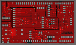
I use Dim Eagle project for the shield and import it in Altium. Here is some pics and finished pcb!
I already read Dim's blog but didn't find the information. I download the manual for the 4.3' TFT from Saint Smart. I just wanna be sure my tft wiring is correct. I already program the Arduino DUE.
I use Dim Eagle project for the shield and import it in Altium. Here is some pics and finished pcb!
Attachments
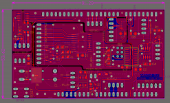
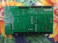
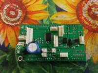
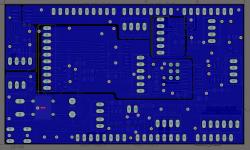
I made my own ES9028pro design, and order the PCB. I use LT3042, and LT3045 for the DAC, LT3042 for the Oscilator, and discrete PSU in vertical boards for the XMOS regulators and I/V convertors. I/V convertors and balansed to single ended convertor are vertical discrete opamps!
The whole idea is try to beat my DIY DAC with PCM63P K2 in audible performance.
The whole idea is try to beat my DIY DAC with PCM63P K2 in audible performance.
Attachments
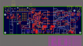
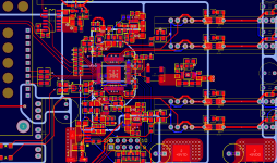
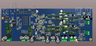
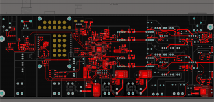
Hi itco I ordered my 9038pro boards psu boards from diyinhk.I made my own ES9028pro design, and order the PCB. I use LT3042, and LT3045 for the DAC, LT3042 for the Oscilator, and discrete PSU in vertical boards for the XMOS regulators and I/V convertors. I/V convertors and balansed to single ended convertor are vertical discrete opamps!
The whole idea is try to beat my DIY DAC with PCM63P K2 in audible performance.
Thank your Dave.
I already read Dim's blog but didn't find the information. I download the manual for the 4.3' TFT from Saint Smart. I just wanna be sure my tft wiring is correct. I already program the Arduino DUE.
I use Dim Eagle project for the shield and import it in Altium. Here is some pics and finished pcb!
If your TFT is this one: 4.3 inch TFT Touchscreen Display for Arduino – SainSmart.com
then its pinout is exactly the same as the 3.2" TFT that I'm talking about here: 3.2″ TFT pinout & connection to Arduino MEGA (or Due) | Dimdim's Blog and here: 3.2″ TFT connection to Arduino Due (UPDATE!!) | Dimdim's Blog
Good job on the PCB.
")
- Home
- Source & Line
- Digital Line Level
- Buffalo III upgraded with ES9028Pro