Gerhard also provided info that the optimum load cap for the LT3042 is 4.7µF. Overdoing gets us a noise peak. Well, 4.7 µF does not seem a problem to me.
Anyone bidding higher than using LT3042/3045 with an output cap of 4.7 µf for feeding DAC chips and/or XO's ?
I recall the LT3045 Data Sheet recommended 10uf on the output, but maybe close enough ? What I am not sure of is what the output cap value should be for multiple parallel LT3045s (for larger current capacity). Does it remain the same, or additive, or what?
A 1.5A Ldover.com module here in front of me has 3 LT3045's and 3 22uf tantalum caps on it. But can't see exactly how they are connected.
I tried an additional 560mfd Kemet Alu. Polymer output cap on a 1.0A Ldovr module, and removed it due to damage to the sound quality. (this also puts doubt on the Stammheim modules, in my mind, due to large output caps)
So a couple more data points but still a bit of a mystery to me

Dave
Last edited:
Are you using a switching power supply and LT3045 as a post regulator?I tried an additional 560mfd Kemet Alu. Polymer output cap on a 1.0A Ldovr module, and removed it due to damage to the sound quality. (this also puts doubt on the Stammheim modules, in my mind, due to large output caps)
The only negative effect of increasing Cout is that "the regulator bandwidth decreases with increasing output capacitance".
I presume you have to avoid the green region you can see in the picture below. If you use a linear power supply to feed LT3045 there is no cause for concern about higher value for Cout.
I successfully use LT3042 (similar to 3045) for AK4490's AVCC with 2 x 1200uF as Cout and I know a few diy-ers who do the same.
Attachments
Indeed, look what can be achieved by stumbling around in the dark
Yes - war, pollution, crime,... it's fantastic
//
The region in the green box shows improvement with higher C!?
//
//
Are you using a switching power supply and LT3045 as a post regulator?
The only negative effect of increasing Cout is that "the regulator bandwidth decreases with increasing output capacitance".
I presume you have to avoid the green region you can see in the picture below. If you use a linear power supply to feed LT3045 there is no cause for concern about higher value for Cout.
I successfully use LT3042 (similar to 3045) for AK4490's AVCC with 2 x 1200uF as Cout and I know a few diy-ers who do the same.
Are you using a switching power supply and LT3045 as a post regulator?
No (not even tempted!), it is fed by a cheap LT1963 module, as a 1st stage, to two 1A series LT3045 modules.
I presume you have to avoid the green region you can see in the picture below. If you use a linear power supply to feed LT3045 there is no cause for concern about higher value for Cout.
I don't understand what is special about the 'green region' ? The chart clearly identifies only two, low Cout values, not the larger values in question.
The only negative effect of increasing Cout is that "the regulator bandwidth decreases with increasing output capacitance"...
I successfully use LT3042 (similar to 3045) for AK4490's AVCC with 2 x 1200uF as Cout and I know a few diy-ers who do the same.
So you are Ok with decreasing your regulator bandwidth. Why ?
Last edited:
The region in the green box shows improvement with higher C!?
//
Are you sure?
Yes, we only have 2 low Cout values, but we can see how PSRR of LT3045 decreases depending of Cout value. An exaggerated picture should explain better than words what I mean, see it bellow.I don't understand what is special about the 'green region' ? The chart clearly identifies only two, low Cout values, not the larger values in question.
So you are Ok with decreasing your regulator bandwidth. Why ?
Yes I am OK with decreasing the regulator bandwidth because I don't have high ripple in my circuit in that area and I don't need LT's higher PSRR. So, I can loose it increasing Cout.
Attachments
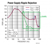
Did you just draw that green curve ? Wow ! Fast and nice. But maybe not so believableAn exaggerated picture should explain better than words what I mean, see it bellow.
Uh, Ok, maybe you don't loose anything audible there. But I still don't understand why you feel the need to increase Cout ??Yes I am OK with decreasing the regulator bandwidth because I don't have high ripple in my circuit in that area and I don't need LT's higher PSRR. So, I can loose it increasing Cout.
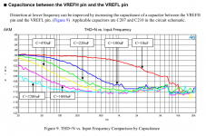
For increasing THD+N at lower frequencies according to the AKM datasheet.Uh, Ok, maybe you don't loose anything audible there. But I still don't understand why you feel the need to increase Cout ??
Attachments
Oh, Ok, you are talking the specific DAC application here. Sorry I was a bit OT, thinking general PSU regulation, and I don't see a need for a large Cout thereFor increasing THD+N at lower frequencies according to the AKM datasheet.
OKOh, Ok, you are talking the specific DAC application here. Sorry I was a bit OT, thinking general PSU regulation, and I don't see a need for a large Cout there
So , back to your initial concern about Cout.
According to LT3045 datasheet:
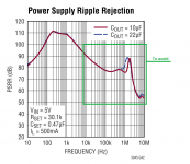
- if recommended 10uF Cout is used, PSRR severely degrades for ripple higher than aprox. 2 MHz , see the graph I have attached in my previous posts.
- if 22uF Cout is used, PSSR severely degrades for ripple higher than aprox. 1.3 MHz
We can see that the increasing of Cout reduces the ripple rejection bandwidth of LT3045, but even for 22uF we are still talking about MHz order frequencies.
Now, you are using a linear power supply which has a ripple at 60 Hz or 120 Hz depends of rectifier, but this ripple is already reduced by LT1963 regulator you use, so I don't understand where your concern about Cout come from?
Why worry in this case if LT3045 ripple rejection bandwidth degrades over 2 MHz, or over 1.3 MHz, or over 0.1 MHz?
I don't understand where your concern about Cout come from?
As I originally said;
"I tried an additional 560mfd Kemet Alu. Polymer output cap on a 1.0A Ldovr module, and removed it due to damage to the sound quality. (this also puts doubt on the Stammheim modules, in my mind, due to large output caps)"
3 or 4 other audiophiles, and myself, have directly experienced a degraded sound quality with larger (560uf in my case) Cout, and someday I might like to try some of Stammheims high current LT3045 modules, but I believe they have even higher Cout's, which gives me pause for their potential SQ contribution (along with their higher prices).
So I'm trying to sort what is going on with LT3045 Cout values, dielectric types, and SQ results. Ok ?
For increasing THD+N at lower frequencies according to the AKM datasheet.
Increasing... THD-N is decreasing in LF at higher C. How are you reading this alt. expressing yourself?
//
A 560uf polymer cap will have an esr value that’s super low, not too many regulators that can work with that. Those parts aren’t very usable in audio unless they are of smaller values like 22uf to 47uf. Might be great filter caps after the diodes though, but haven’t tried it.
Most regulator data sheets have these ratings that will suggest a certain range of esr for a given regulator, and if you use the appropriate parts within that range, things work pretty good I have found. Trace lengths will give up some of that if they are longer, have to consider that too.
If you can’t find the listed values in a data sheet, often the parts are made by several manufacturers and sometimes the various data sheets will have information not found on the others.
OK
So , back to your initial concern about Cout.
According to LT3045 datasheet:
- if recommended 10uF Cout is used, PSRR severely degrades for ripple higher than aprox. 2 MHz , see the graph I have attached in my previous posts.
- if 22uF Cout is used, PSSR severely degrades for ripple higher than aprox. 1.3 MHz
We can see that the increasing of Cout reduces the ripple rejection bandwidth of LT3045, but even for 22uF we are still talking about MHz order frequencies.
Now, you are using a linear power supply which has a ripple at 60 Hz or 120 Hz depends of rectifier, but this ripple is already reduced by LT1963 regulator you use, so I don't understand where your concern about Cout come from?
Why worry in this case if LT3045 ripple rejection bandwidth degrades over 2 MHz, or over 1.3 MHz, or over 0.1 MHz?
With LT3045 you might not need the huge cap to achieve the THD performance that AKM shows with the 2200uF cap. I'm not sure what regulator they use on their evaluation board, but I am sure it is a lot noisier at low frequencies than the LT3045. That huge cap is just pushing the corner frequency of the filter lower.
3 or 4 other audiophiles, and myself, have directly experienced a degraded sound quality with larger (560uf in my case) Cout[...]
I missed that part - about audiophiles, it is about the perception, everybody has it's own datasheet. Good luck.
You are right, it is about decreasing distortions, but not increasing them, of course.Increasing... THD-N is decreasing in LF at higher C. How are you reading this alt. expressing yourself?
//

You are right too, I thought the graph expresses itself:I noticed something similar earlier with the PSRR graphs. The comment was just the opposite of what the curves showed.
Jan
I referred to the bandwidth limitation region of the graph only. If Cout is 22uF, you are right - PSRR increases, but the inflection point of the graph is moving to the left and as you can see, if there is a ripple in the input circuit to aprox. 1.8Mhz is better for Cout to be 10uF because in the 22uF situation PSRR is already descending.
I admit it may look strange to someone who cannot read my thoughts.
A 560uf polymer cap will have an esr value that’s super low, not too many regulators that can work with that. Those parts aren’t very usable in audio unless they are of smaller values like 22uf to 47uf. Might be great filter caps after the diodes though, but haven’t tried it.
Most regulator data sheets have these ratings that will suggest a certain range of esr for a given regulator[...]
In this case low esr is good:
"For stability, use a minimum 10µF
output capacitor with an ESR below 20mΩ and an ESL
below 2nH. Large load transients require larger output
capacitance to limit peak voltage transients.[...]
Given the high PSRR and low noise performance attained
using a single 10µF ceramic output capacitor, larger values
of output capacitor only marginally improves the perfor-
mance because the regulator bandwidth decreases with
increasing output capacitance — hence, there is little to
be gained by using larger than the minimum 10µF output
capacitor. Nonetheless, larger values of output capacitance
do decrease peak output deviations during a load transient."
I just reviewed my project and I have seen there are 2 for VREFleft and 2 for VREFright, so 4x1200uF 8 mOhm ESR each for a single LT3042 - 7V output.
I will make some measurements and I will post the results.
Totally agree, actually I am almost convinced about that, but initially my project was intended to be powered up by another power supply. I am also convinced that this huge cap has no negative effect.With LT3045 you might not need the huge cap to achieve the THD performance that AKM shows with the 2200uF cap. I'm not sure what regulator they use on their evaluation board, but I am sure it is a lot noisier at low frequencies than the LT3045. That huge cap is just pushing the corner frequency of the filter lower.
I also though it was odd to suggest such a huge part for something that requires such a tiny amount of power instead of another means to a quiet source. I tried it and it worked with an lt1963, but was tempted to shield and ground the thing!
The eval board uses a discreet reg with an op amp, transistors.
The huge polymer will definitely be lower esr, just have to watch for interactions with other parts, I haven’t been able to use the large ones I have here, as they ring, but maybe that is just the regulators I am using.
The eval board uses a discreet reg with an op amp, transistors.
The huge polymer will definitely be lower esr, just have to watch for interactions with other parts, I haven’t been able to use the large ones I have here, as they ring, but maybe that is just the regulators I am using.
- Home
- Source & Line
- Digital Line Level
- Low noise regulator for DAC & clock