hi
for year i use the ad1865 DAC, i build fine PS and i use current output.
decide to do some test with my new spectrum analyzer:
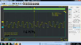
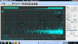
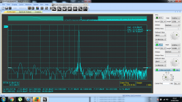
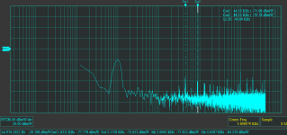
for 1KHz wave, the results are fine for NOS DAC (i think), but when i try 15KHz i get another frequency at 1.2KHz and 200Hz
i think of Nyquist, because for 44KHz sample, 20khz look like rectangular, so maybe 15hkz look close?
thanks
for year i use the ad1865 DAC, i build fine PS and i use current output.
decide to do some test with my new spectrum analyzer:
for 1KHz wave, the results are fine for NOS DAC (i think), but when i try 15KHz i get another frequency at 1.2KHz and 200Hz
i think of Nyquist, because for 44KHz sample, 20khz look like rectangular, so maybe 15hkz look close?
thanks
Attachments
"You're not filtering out the image frequencies " you are right.
just to clear things: as i remember perfect 15Khz pulse not have aliasing in the audio BW, only 22KHz >>. but here the alising is from the 15KHz 2nd harmonic?
the solution for this is 2.2nf in parallel to R I/V ?
thanks
just to clear things: as i remember perfect 15Khz pulse not have aliasing in the audio BW, only 22KHz >>. but here the alising is from the 15KHz 2nd harmonic?
the solution for this is 2.2nf in parallel to R I/V ?
thanks
A first order filter will be of help, but only barely. I can only guess that your I/V resistor will be of the order of 1k so in parallel with 2n2 this'll give a corner frequency of 72kHz. So the first set of images (below 44k1) won't be affected at all.
There will be very little harmonic distortion as compared to the presence of image products.
There will be very little harmonic distortion as compared to the presence of image products.
A first order filter will be of help, but only barely. I can only guess that your I/V resistor will be of the order of 1k so in parallel with 2n2 this'll give a corner frequency of 72kHz. So the first set of images (below 44k1) won't be affected at all.
There will be very little harmonic distortion as compared to the presence of image products.
50 ohm R i/v
i add 40nf cap, help little bit, now the SNR in 1Khz is 60DB.
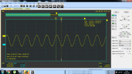
also the 10khz sin wave not look good, maybe its the sample rate?
so everyone live with the noise in high frequency? i dont see many in the NOS community that talk about that, maybe that’s the whey the DAC works.
thanks
50 ohm R i/v
i add 40nf cap, help little bit, now the SNR in 1Khz is 60DB.
With 42nF and 50ohm your corner frequency is 76kHz. Still inadequate to make an impression on the strongest image frequencies.
also the 10khz sin wave not look good, maybe its the sample rate?
If you want your DAC's output to look good on the 'scope, consider a much sharper filter. I have several examples on my blog using inductors and capacitors.
so everyone live with the noise in high frequency? i dont see many in the NOS community that talk about that, maybe that’s the whey the DAC works.
Pretty much all the NOS guys don't much care about the images, you're correct. Some even think that having 'perfect' squarewave pictures on the scope is a bonus point for NOS. I'd put this down to groupthink myself.
If you don't filter the images away then they will be present; the level depends on frequency. NOS people either don't know this, or don't worry about it. If images are present then some test equipment may be confused, or the equipment user may be confused.
now im confuse, alising happen when we sample more then 2*f of fsample.
only the spectrum sample here.
the DAC receive PCM not more than 20KHz. (i think)
when i send 15KHz PCM to the DAC its play 15KHZ wave, in the F-domain it has 30K and 45K component etc. so this issue its only the spectrum sample rate?

investigate the noise in the circuit i learn more thing, the SPDIF with fine transformer make noise too in the audio domain ( or its alising too

so the solution its not on the DAC? the LPF need Should be kept at the probe entrance always?
Yes, you are confused. You are confusing aliasing (happens if the low pass filter before the ADC is inadequate or missing) with imaging (happens if the low pass filter after the DAC is inadequate or missing). A common mistake. Filterless NOS DACs suffer from imaging. Aliasing, if present, happens at the recording or mastering stage so is outside your control.erez1012 said:now im confuse, alising happen when we sample more then 2*f of fsample.
only the spectrum sample here.
thanks DF96
very happy to back to university days, but now the Theory more practical.
a lot of reading for this subject now.
i see in the spectrum the imaging frequency, i understand that if i want to go NOS i need some filter, i prefer passive one. but still i have issue in 18khz, but its OK
thanks abraxalito for your filter, i tray it, look for Replacement Inductor for fast testing the filter.
Attachments
Last edited:
You're not filtering out the image frequencies so you may well be seeing aliasing artifacts from your analyser. The zero-order hold attenuates the images of 1kHz to a much greater extent than 15kHz.
If the observed spectra were the result of FFT aliasing, it would also appear in the 1K plot. It can’t be an unfiltered image because the first image contains frequencies above the Nyquist frequency. The problem is the output of the DAC in question is not zero-order hold because the output is not steady during the each sample period. Notice the slope in the stair steps. The FFT is showing the frequency components of those slopes. It looks like high impedance in the power rails supplying the DAC chip. Most likely inadequate bypassing or long, hair-thin traces feeding power and ground.
- Status
- This old topic is closed. If you want to reopen this topic, contact a moderator using the "Report Post" button.
- Home
- Source & Line
- Digital Line Level
- NOS dac, 15KHz wave test Strange results