Hi guys,
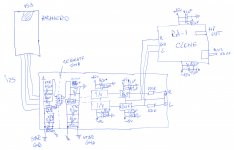
I'm building a DAC based on PCM1794A from TI with I2S fed from an Amanero USB -> I2S card. As I want to have also adjustable HP out, I will use a Grado RA-1 clone circuit for that.
I ordered a custom 21VA transformer with 2 secondaries: 13v-0-13v (26VAC) for the OPAMPS and 5VAC for feeding the too LDO's on the DAC's PCB: Burr Brown REG101 for the 5v and TI LM2937-3.3 for the 3.3v.
Can you please check the attached schematics and let me know if they are ok? For the decoupling HF in the PSU I used WIMA MKS2 100nf, should I keep these or change to X7R ceramics?
Attachments
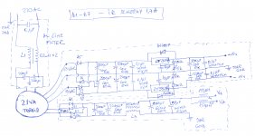
Separate ground means that the AGND and DGND is kept separate on the DAC PCB and united just in one point at the star ground location, near the PSU.
I also thought about I2S isolator but it's pretty expensive and may introduce some latency, while the measurable jitter reduction is not so noticeable.
I also thought about I2S isolator but it's pretty expensive and may introduce some latency, while the measurable jitter reduction is not so noticeable.
Thanks for the input guys!
@Redshift187: I read somewhere in an Analog Devices study that it's better to unite AGND and DGND in a single place, at the PSU. There are also opinions that back to back Schottky or inductors should be use to connect them, so I don't know what the best solution would be...
@abraxalito: I used two 2200uF caps in parallel because I have a big stock of new Rubycon ZL. I guess you are suggesting the impedance there to do some kind of CLC / CRC filter, but I already took care of that with the CM choke placed after them. Am I wrong here?
Any other things that I should change at the PSU?
Common-mode chokes are for filtering common-mode noise, however noise occuring on power supplies is normal-mode (i.e. differential). CM chokes have very little effect on differential mode noise unless they have high leakage inductance. CRC filters and CM chokes are complementary in other words.
You'd do well to introduce CRC on the other trafo tap, that feeding the LM317/337, not just the supply with the CM choke. Reason being active regulators tend to suck pretty bad at HF rejection, passive filters do mostly OK though, within ESR limits.
You'd do well to introduce CRC on the other trafo tap, that feeding the LM317/337, not just the supply with the CM choke. Reason being active regulators tend to suck pretty bad at HF rejection, passive filters do mostly OK though, within ESR limits.
CM choke also act as a filter if their value is high enough, correct? Or maybe it's better to make the two windings in series to have higher inductance and put it just on the + side. The choke I use is the Coilcraft CMT4-125-1L
For the other circuit should I put 10ohm 5W resistor between the two 2200uF capacitors?
For the other circuit should I put 10ohm 5W resistor between the two 2200uF capacitors?
If the leakage inductance is high enough it'll act as a significant series impedance for sure. Trouble is the leakage inductance isn't too predictable so that's not an effective way to design a filter. A filter design needs a predictably stable inductance.
The value of series resistor depends on how much voltage you can afford to drop prior to your regulator - the regulator normally needs at least 2V across it (depends on output current) to remain in regulation. To dissipate 5W you'd have 7V across this resistor meaning you're drawing 700mA which seems a little bit high so probably you don't need as large a resistor as 5W. However no harm in choosing a higher rated resistor than required apart from space and cost.
The value of series resistor depends on how much voltage you can afford to drop prior to your regulator - the regulator normally needs at least 2V across it (depends on output current) to remain in regulation. To dissipate 5W you'd have 7V across this resistor meaning you're drawing 700mA which seems a little bit high so probably you don't need as large a resistor as 5W. However no harm in choosing a higher rated resistor than required apart from space and cost.
The choke I'm using has 1400uH leakage inductance so it's pretty ok, but as you say it's not predictable. I think it should be better to use this CM choke with the windings in parallel / series, what do you think?
Another option would be to ditch the CM chokes and use a simple CRC filter on all the secondaries, filtering differential noise with ferrite beads (150uH) when connecting the +15v, -15v, Vd and Va at the DAC PCB.
Thanks a lot for your input!
Another option would be to ditch the CM chokes and use a simple CRC filter on all the secondaries, filtering differential noise with ferrite beads (150uH) when connecting the +15v, -15v, Vd and Va at the DAC PCB.
Thanks a lot for your input!
Reversing one winding on the CM choke will most certainly give you a huge bump in inductance. There's no free lunch though, the consequence will be that your inductor will saturate at a very low current, I'm guessing just a few 10s of mA. Which you may not notice at all but means you'll have very little filtering effect, just like having RC rather than LC as filter.
Caps in parallel with res caps? I'd not bother myself.
Caps in parallel with res caps? I'd not bother myself.
- Status
- This old topic is closed. If you want to reopen this topic, contact a moderator using the "Report Post" button.
- Home
- Source & Line
- Digital Line Level
- Home made Amanero + PCM1794A DAC (opinion needed)