ok i have one more question.
case 0: // Auto detect which supports "32bit I2S, DSD or SPDIF"
// This is default conf. SPDIF can be connected to DATA_CLK line
bitClear(reg11S,4); // Default setting for SPDIF
bitClear(reg11S,5); // Default setting for SPDIF
bitClear(reg11S,6); // Default setting for SPDIF
writeSabreReg(0x0B,reg11S); // Reg 11: x 0 0 0 x x x x
writeSabreReg(0x01,0x8C); // Set to auto mode: 1 0 0 0 1 1 0 0
lcd.print("AUT");
break;
This screch do not setup format, yes?
I add new line:
case 3: // Auto detect which supports "32bit I2S, DSD or SPDIF"
// This is default conf. SPDIF can be connected to DATA_CLK line
bitClear(reg11S,4); // Default setting for SPDIF
bitClear(reg11S,5); // Default setting for SPDIF
bitClear(reg11S,6); // Default setting for SPDIF
writeSabreReg(0x0B,reg11S); // Reg 11: x 0 0 0 x x x x
writeSabreReg(0x01,0x8C); // Set to auto mode: 1 0 0 0 1 1 0 0
writeSabreReg(0x0A,0xDE);
lcd.print("RJA");
break;
case 4: // Auto detect which supports "32bit I2S, DSD or SPDIF"
// This is default conf. SPDIF can be connected to DATA_CLK line
bitClear(reg11S,4); // Default setting for SPDIF
bitClear(reg11S,5); // Default setting for SPDIF
bitClear(reg11S,6); // Default setting for SPDIF
writeSabreReg(0x0B,reg11S); // Reg 11: x 0 0 0 x x x x
writeSabreReg(0x01,0x8C); // Set to auto mode: 1 0 0 0 1 1 0 0
writeSabreReg(0x0A,0xEE);
lcd.print("LJA");
break;
Correct?
Register #10: Mode Control 1 (default = 8’b11001110)
[7:6] : 24/20/16 Bit for Serial Data Modes.
2’b00 = 24Bit
2’b01 = 20Bit
2’b10 = 16Bit
2’b11 = 32Bit
[5:4] : LJ/I2S/RJ Serial Data Modes.
2’b00 = I2S
2’b01 = LJ
2’b10 = RJ
2’b11 = I2S
[3] : RESERVED Must be set to 1’b1 for normal operation.
[2] : JITTER_REDUCTION_ENABLE.
7 6 5 4 3 2 1 0 bit
x x x x x x x x pos
1 1 0 0 1 1 1 0 def is2 0xCE
1 1 0 1 1 1 1 0 LJ 0xDE
1 1 1 0 1 1 1 0 RJ 0xEE
Power supply for ESS DAC


My search led me to the same LDO regulator IC that fluid used, but I got PSU boards from Chinese sellers and toroidal transformer from Antek. It is interesting to see how the power supply dominate the enclosure in fluid's picture. In my setup, the transformer and LT1084CP PSU will be in a separate box.
I am updating the PSU for a ES9038Q2M based DAC.I thought I would post some pictures and info about the diyinhk ES9018k2m DAC that I just finished building.
I have an older board so there is 3.3v and 5v diyink TPS7A4700 power supplies. The opamp is powered by a fairly basic bipolar LT1084 supply from Analog Metric.
My search led me to the same LDO regulator IC that fluid used, but I got PSU boards from Chinese sellers and toroidal transformer from Antek. It is interesting to see how the power supply dominate the enclosure in fluid's picture. In my setup, the transformer and LT1084CP PSU will be in a separate box.
wchpikus said:ok i have one more question.
I'm not sure what it is exactly that you are trying to set.
It might be easier to just write a simple sketch that only sets the basic registers to the values that you want and change them until you get it working. Once you know the right values you could easily put them into the hifiduino code if you want the menu and volume control etc.
I have to have in menu RJ for my purpose.
I tested this 10 register but do not work.
This dac is not used for listen music, only for testing enduser device before sending.
At this moment i do not have any dac support RJ and i test then to LJ (wt32) and after sending i switch i2s on the wt32 to RJ (without confirm correct setup).
It will be great to test RJ to be sure,if all is ok.
Could you help to add this?
Register 10 is the one that will change the format of the signal the DAC is looking for. If that isn't working then it is possible the data coming out is not what the DAC expects to find and so it won't play. In the 9018 data sheet it has a diagram of the structure of the different types of data, short of trying the other types or analysing the data from the device to see what format it really is I don't have any other ideas, sorry.
spdif ttl input
Hi,
I have built exactly the same project and i have a question about GPIO2 input
When i connect the 3.3V output from a pcm2704 it works fine
When i connect the coaxial output from a cd-player it plays for a few seconds and then stops. There is no lock. Now cd-player it cant lock at all. pcm still works. I havent have another cd-player to try
While i was googling.. for an answer i read that some devices need TTL level to work properly. Is this the solution to the specific problem?
Last edited:
The active parts are hex inverters which are often used in this sort of circuit. I can't say from looking if that will work as you want.
Have a look at this page in the Appendix section
S/PDIF Digital to Analogue Converter

Have a look at this page in the Appendix section
S/PDIF Digital to Analogue Converter
Attachments
Hello,
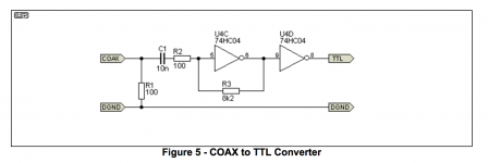
This is the first result of searching for ttl converters
I inspired by this and a couple more that have the same idea
I want to add an isolation trany to avoid the PC noisy ground
The voltage supplied is supposed to be 3.3Vdc
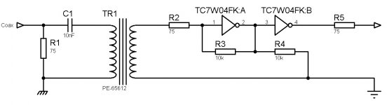
Below is my way of thinking
R1 is the 75Ω spdif termination and C1 blocks DC coupling
The Trany is the PE-65612
R3 and R4 works as a voltage divider to supply a bias point of Vcc/2 to the input of the 1st inverter. I dont know if that thought is correct
For the hex inverter i choose the TC7W04 because it has 3 stages of two that i need
R2 and R5 i suppose is some kind of limiter
Please correct me if something goes wrong either for coponent's value or camponent selection or my way of thinking
Thanks
This is the first result of searching for ttl converters
I inspired by this and a couple more that have the same idea
I want to add an isolation trany to avoid the PC noisy ground
The voltage supplied is supposed to be 3.3Vdc
Below is my way of thinking
R1 is the 75Ω spdif termination and C1 blocks DC coupling
The Trany is the PE-65612
R3 and R4 works as a voltage divider to supply a bias point of Vcc/2 to the input of the 1st inverter. I dont know if that thought is correct
For the hex inverter i choose the TC7W04 because it has 3 stages of two that i need
R2 and R5 i suppose is some kind of limiter
Please correct me if something goes wrong either for coponent's value or camponent selection or my way of thinking
Thanks
Attachments

Last edited:
R1 and C1 form a low pass filter the pulse transformer is a common part used in these type of circuits as for the rest I have no experience with these parts so I can't offer much of an explanation, I suspect the other 75 ohm resistors in series are set to set the impedance.
I like Rod Elliot's circuit because it is simple and he is a reliable source of information. If you want you could insert the transformer into that circuit for isolation.
I like Rod Elliot's circuit because it is simple and he is a reliable source of information. If you want you could insert the transformer into that circuit for isolation.
- Status
- This old topic is closed. If you want to reopen this topic, contact a moderator using the "Report Post" button.
- Home
- Source & Line
- Digital Line Level
- ES9018k2m Build Completed