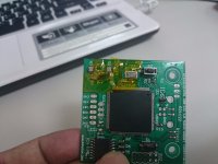
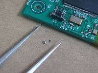
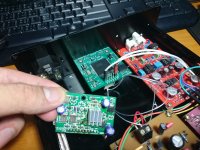
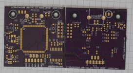
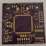
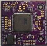
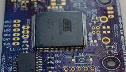
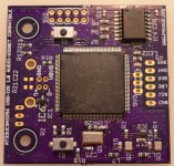
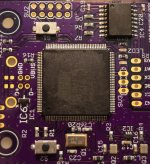
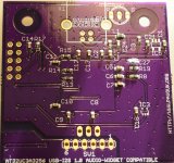
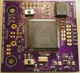
One day, I've decided to build Pavouk's USB to I2S project which my friend suggested me to do. This board including isolation of I2S which isolates the signal and ground from PC to DAC. And I send files to PCB maker for making customized PCB. After the PCB is done, it takes another months to collect the materials and finally, after making several mistakes, I started to solder the components. The easiest component was, surprisingly, the AT32UC3A3256 chip (it has 144 pins), and the most difficult component was the oscillator (4 pins only). (resistors and caps are between them)
The project page:
http://www.pavouk.org/hw/audiosystem20/en_at32uc3a3256usbi2s.html
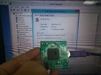
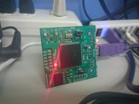
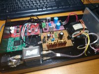
The firmware was the one for Henry AudioUSB DAC 128 mkII with volume control fix. I programmed the FW in Windows 'cause it always shows error when I programmed in Ubuntu. When I connected it to the PC, it just works well. But Windows doesn't support UAC2 in kernel, I just able to play music in 16bit 44.1/48 kHz in UAC1 mode. I put it on my DAC (PCM1704) replacing XMOS. Surprisingly, it sounds better than XMOS (I do made an isolation circuit for XMOS using ISO7640FM). I thought it is due to bad component (maybe OSC?) in XMOS board or something wrong with my ear but I'm not sure for this. I played music in foobar in UAC2 mode through ASIO driver, unfortunately, it sounds worse and flat than in UAC1 mode which sampling rate just match the format of the music file.
This board just designed well but it would be great if it has more space for fitting different type of oscillators and bigger LDO chip. The size of 2.5 x 2.0mm is just too small and not available for hi-end oscillator.
This was my first cloning project of digital circuit.
Please feel free to give some suggestion.
The project page:
http://www.pavouk.org/hw/audiosystem20/en_at32uc3a3256usbi2s.html
The firmware was the one for Henry AudioUSB DAC 128 mkII with volume control fix. I programmed the FW in Windows 'cause it always shows error when I programmed in Ubuntu. When I connected it to the PC, it just works well. But Windows doesn't support UAC2 in kernel, I just able to play music in 16bit 44.1/48 kHz in UAC1 mode. I put it on my DAC (PCM1704) replacing XMOS. Surprisingly, it sounds better than XMOS (I do made an isolation circuit for XMOS using ISO7640FM). I thought it is due to bad component (maybe OSC?) in XMOS board or something wrong with my ear but I'm not sure for this. I played music in foobar in UAC2 mode through ASIO driver, unfortunately, it sounds worse and flat than in UAC1 mode which sampling rate just match the format of the music file.
This board just designed well but it would be great if it has more space for fitting different type of oscillators and bigger LDO chip. The size of 2.5 x 2.0mm is just too small and not available for hi-end oscillator.
This was my first cloning project of digital circuit.
Please feel free to give some suggestion.
Attachments
-
 5KnfHOgMnqazE6zpW15ukQ.jpg126.1 KB · Views: 757
 -
 5jMu4BxSw0GMvKjJRbWyPu.jpg164.4 KB · Views: 754
 -
 7hwpWvFqtHkOmfCAUetjGf.jpg214 KB · Views: 752
 -
 4T06oFTZWX2seCXsjHpGjC.jpg132.2 KB · Views: 743
 -
 6GGRRDGjnA8vviAsC72yK2.jpg234.4 KB · Views: 923
 -
 75uIBoXNx1oRzOfbnGIRiw.jpg210.4 KB · Views: 252
 -
 6wCAh1wuCXx2STKBR4gDRz.jpg214 KB · Views: 247
Last edited:
it sounds better than XMOS
The Isolation breaks up ground loops between computer and DAC. This would explain the improved sound.
But there is more room for improvement.
In this design, the Atmel seems to run on a multiple of 12 MHz (internal frequency multiplier). It differs from the external audio clocks of 22.5792 or 24.576 MHz.
Similar situation with the XMOS, runs on a multiple of 26 MHz. This results in approx. 2000ps jitter on all I2S pins. Unless I am wrong you could have a similar issue with this application.
This jitter is added to the opto coupler jitter that is specified at approx. 1000ps.
So you could end up with approx. 3000ps of jitter on the isolated I2S interface signals BCK, WS, and DATA and approx. 1000ps jitter on the isolated SCK output.
Not really great isn’t it?
So this is what I would suggest:
Use IL715 isolators instead, here is why (check the jitter specs):
https://hifiduino.wordpress.com/2011/11/24/which-digital-isolators-for-i2s-or-not/
If I am correct these have (almost) the same pin layout so it should not be difficult to use these on the existing board.
Then we need to get rid of the 2000ps of jitter on the Atmel I2S pins. It can be fixed easily by synchonously reclocking the I2S signals. Using 3 x 74LVC1G79 flip flop for example. Data input goes to the Atmel I2S pin, clock inputs all go to pin 2 of IC3 (non-inverted audio clock).
The low jitter I2S signals can be taken from the flip flop Q outputs and fed to the digital isolator inputs.
These flip-flops only have 5 pins:
1 = Data input
2 = Clock input
3 = Vss (0V)
4 = Q output (non-inverted)
5 = Vdd (3V3 for example)
If there is an issue with phase (distorted sound) you might want to invert the audio clock that connects to the Flip-flops. With the XMOS all worked fine with an inverted audio clock routed to the XMOS and a non-inverted audio clock routed to the flip-flops.
The IL715 will add 100ps, you have to live with that, either way it’s a significant improvement compared to approx. 3000ps jitter in the original design.
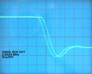
I attached an oscillogram of the jitter that I measured on an I2S pin (BCK) of the XMOS. The jitter amplitude equals approx. 2 sub divisions (2ns or 2000ps peak to peak).
After synchronous reclocking with the 74LVC1G79 you would measure a single transient and greatly reduced jitter level.
After synchronous reclocking with the 74LVC1G79 you would measure a single transient and greatly reduced jitter level.
Attachments
Thanks for detailed reply.
But,
you'll find that (you are close to the screen, of course) I do made an isolation circuit when using XMOS. The ISO7640 chip just behind Pavouk's board.
Correct me if I got it wrong.
But,
If you see very close to the picThe Isolation breaks up ground loops between computer and DAC. This would explain the improved sound.
you'll find that (you are close to the screen, of course) I do made an isolation circuit when using XMOS. The ISO7640 chip just behind Pavouk's board.
Correct me if I got it wrong.
Last edited:
Reviving an old thread, but I will be building two of these boards when I've recieved all parts and the PCB's.
Currently trying to get all SW running on Ubuntu 17.04 64bit.
Managed to break the OS lol
I have got the SW running on Linux mint 32-bit now though.
I sent the .brd file to oshpark for fabrication.
So I suppose it is exactly the same.
I am waiting for the second shipment of parts, it should've arrived today...but Swedish postal service is not what it used to be...
AND, I haven't recieved the boards yet. I went with 2oz Cu so turn-around time was a bit longer.
So I suppose it is exactly the same.
I am waiting for the second shipment of parts, it should've arrived today...but Swedish postal service is not what it used to be...
AND, I haven't recieved the boards yet. I went with 2oz Cu so turn-around time was a bit longer.
Not sure tbh, it took me several days to get the sw installed and understand(I think lol) how to use it.
Completely new to this stuff as well. Searched around on the web, the most helpful was the github readme(s) and some search results I got when searching as problems/roadblocks occured.
Completely new to this stuff as well. Searched around on the web, the most helpful was the github readme(s) and some search results I got when searching as problems/roadblocks occured.
I understand...
A friend of mine told me that this project goes until 192K sampling, is that true?
Why not the 352/384 and dsd?
Amanero with different version of Atmel goes well...
As mine will likely never see a signal above 192Khz, I have not looked into that.
It follows UAC1 and UAC2 standards from my limited understanding. Maybe looking at those, and looking at sites like henry audio etc that use this MCU can give you a clearer picture of the capabilities of this IC used in the way it is here?
Links I found useful
Pavouk
How to install AVR 32-bit Toolchain on Linux Aery32 DevZone
https://github.com/borgestrand/sdr-widget/tree/audio-widget
The ζ1 Audio Widget asynchronous USB-I²S module
https://github.com/borgestrand/sdr-widget/tree/audio-widget-experimental
Henry Audio - Open Source USB DAC
https://groups.google.com/forum/?hl=en#!forum/audio-widget
Hmm...I read at the link The ζ1 Audio Widget asynchronous USB-I²S module
"UAC2 (USB 2.0 high speed): up to 32 bits; 44.1KHz, 48KHz, 88.2KHz, 96KHz, 176.4KHz and 192KHz sample rates".
Thanks for links.
"UAC2 (USB 2.0 high speed): up to 32 bits; 44.1KHz, 48KHz, 88.2KHz, 96KHz, 176.4KHz and 192KHz sample rates".
Thanks for links.
")
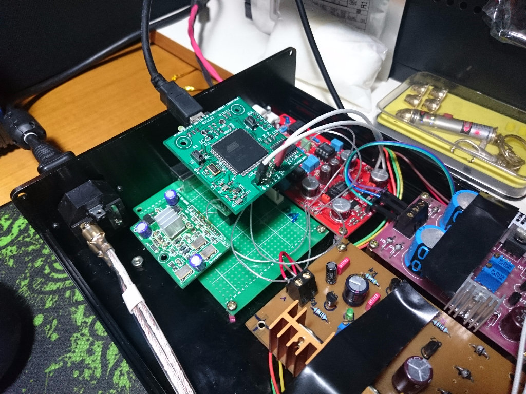
Got some additional parts populated today. I did notice I'd missed to order the LP2992AIM5-3.3 and I had gotten 74LVC1G80's with the wrong footprint.
Ordered both this morning, should get them during next week.
I need to reflow/clean up a few things (good thing about having a decent DSLR is spotting that stuff in pics, when you don't have a USB-microscope).
There's cotton from a q-tip from when I cleaned the board on one of the C0G/NP0 caps.
Ordered both this morning, should get them during next week.
I need to reflow/clean up a few things (good thing about having a decent DSLR is spotting that stuff in pics, when you don't have a USB-microscope).
There's cotton from a q-tip from when I cleaned the board on one of the C0G/NP0 caps.
Attachments
- Status
- This old topic is closed. If you want to reopen this topic, contact a moderator using the "Report Post" button.
- Home
- Source & Line
- Digital Line Level
- Building Pavouk's Async USB to I2S