By the way, I have a few STM32F4 Discovery boards, a few STM32F401 Nucleo boards, and a few STM32F411 Nucleo boards.
I have two ST-Link-V2, and one RealView ULINK2, just in case.
A few months ago, I considered ordering a few STM32F746 Nucleo boards, but after realizing that my other Nucleo boards were piling up because of the Async USB audio issue, I renounced.
I also have WM8580A multichannel codecs, quartz or oscillators, SMD capacitors, SMD resistors, SMD voltage regulators, TDA7802 I2S-in amplifiers, PCM5102A DACs, etc. Some are five years old. The markings on the Digi-Key, Farnell and Mouser labels tend to fade.
I also have a few Dacberry2 v1.1 boards, those are the ones embedding a PCM5102A DAC. Should be easy to hook a few of them on a STM32F4xx Nucleo.
I am anxious to test the STM32F4 USB Audio functionality that you have achieved. Testing it may render me less pessimistic, about the feasibility of Async USB audio (receive) on the STM32F4 or STM32F7.
Succeeding on the Async USB audio functionality, would be fantastic bonus, opening many doors to the STM32F4 and STM32F7, and the ones able to program them.
Cheers,
Steph
Last edited:
I'll go forward ") even if it may be slow... Two weeks leaves will take me far form that project, but I hope to have something by the end of summer on the stm32F4 discovery, with USB in (the one provided by ST) => DSP => I2S=> onboard DAC + another I2S not connected to anything.
even if it may be slow... Two weeks leaves will take me far form that project, but I hope to have something by the end of summer on the stm32F4 discovery, with USB in (the one provided by ST) => DSP => I2S=> onboard DAC + another I2S not connected to anything.
This will be the basic template for the stm32F7 project with SPDIF output.
As I have 2 left hands and not enough knowledge, I have to keep the hardware part as minimal as possible.
JMF
even if it may be slow... Two weeks leaves will take me far form that project, but I hope to have something by the end of summer on the stm32F4 discovery, with USB in (the one provided by ST) => DSP => I2S=> onboard DAC + another I2S not connected to anything.This will be the basic template for the stm32F7 project with SPDIF output.
As I have 2 left hands and not enough knowledge, I have to keep the hardware part as minimal as possible.
JMF
I understand your goal of wanting USB as maximum-quality audio source.
Try a sub-$100 USB to I2S converter like the AMANERO Combo 384. It is here : AMANERO Combo 384 Digital Interface USB 384kHz to I2S/DSD
Pin 6 (OUT_MCLK) of the AMANERO Combo 384 needs to be routed to the Audio Clock In of the STM32F4 or F7, to be used as global master audio clock. All I2S and all SAI in I2S protocol to exploit such clock. It should be 256 x Fs.
Please note the two quartz oscillators, one for the 48 kHz-related sampling frequencies, the other for the 44.1 kHz-related sampling frequencies.
This is the proof that the AMANERO Combo 384 will always be the audio clock master, and jitter-free, whatever the sampling frequency.
The doc says it supports Async USB audio.
Less expensive, we have the $35 miniDSP miniStreamer. It is here : miniDSP ministreamer
Pin 8 (MCLK OUT) of the miniDSP miniStreamer needs to be routed to the Audio Clock In of the STM32F4 or F7, to be used as global master audio clock. All I2S and all SAI in I2S protocol to exploit such clock. It should be 256 x Fs. I guess it can't be changed, unless the "by default" windows driver enables such thing.
I can see one quartz oscillator, not two. I guess there is a PLL somewhere. Not sure all sampling frequencies are guaranteed to come jitter-free.
Async USB audio supported ?
It would be interesting to compare those two external USB to I2S modules.
What's regarding "bit perfect".
And what's regarding jitter.
One can design smart measurement gear relying on a STM32F4 or F7.
Say a dual I2S data grabber for the bit perfect test (for your eyes, appreciating the data deviation).
Say a dual LRCK mixer, analog (for your ears, appreciating the jitter).
Think about it ...
Because of relying on a USB to I2S module, the STM32F4 or F7 doesn't need to deal with the USB protocol, and thus, there is no precise 48 MHz clock required. The STM32F4 or F7 could thus rely on their built-in RC oscillator, instead of a 16 MHz quartz.
Knowing this, you should rely on STM32CubeMX for configuring the STM32F4 or F7 clocks, peripherals, and pinout.
Decide who will act as I2S master. Will it be the USB to I2S module or will it be the STM32 ?
Make sure you understand the difference between I2S master/slave and MCLK clock master.
Check the MCLK frequency the USB to I2S module is actually outputting. Add some frequency divider (hardware) if required. It may be a tiny IC like the CS2000 tjaekel featured on his DIGI-STM board. The CS2000 gets controlled by a I2C bus. Apparently, he relies on a 24,576 kHz quartz oscillator as master clock, then divide it by a certain factor, eventually fractional, for attaining all common audio frequencies like 12,288 kHz (48 kHz) or 11,2896 kHz (44.1 kHz).
Configure the STM32F7 I2S that's receiving the audio data, in such a way that it generates an interrupt each time there is new audio data available. Such audio interrupt should recur at 48 kHz.
Organize the software as an endless main_loop, possibly void as basically, there are no other tasks than the audio.
Write the audio interrupt in assembly.
There is no need for a context save/restore in case the main_loop remains void.
In assembly, four lines of code generate a 32-bit precision IIR Biquad filter.
How many do you need ?
- 4 on the left channel as global parametric pre-equalizer
- 4 on the right channel as global parametric pre-equalizer
- 2 for making the left woofer (4th-order lowpass)
- 2 for making the right woofer (4th-order lowpass)
- 2 for making the left tweeter (4th-order highpass)
- 2 for making the right tweeter (4th-order highpass)
Total : 16 IIR Biquads.
Each IIR BiQuad should take 4 lines of assembly code.
Your audio code shouldn't exceed 64 lines of assembly code.
The IIR Biquads coefficeints can be constants, easily editable through the software development environment. They can also reside in an array in RAM, accessed by a pointer.
Say each IIR BiQuad takes 10 cycles, it means that the whole audio interrupt consumes 160 cycles.
This corresponds to 2 µs in case your STM32F4 or F7 gets clocked at a lazy 80 MHz. Remember that the 48 kHz recurrence of the audio interrupt, corresponds to a maximum 20 µs execution time for the audio interrupt, which situates the limit at approx 160 IIR Biquads. You'll never be able to manage 160 IIR Biquads in an meaningful way, in the context of a stereo crossover.
Rely on a GPIO and a scope for monitoring the system load. Turn the GPIO on upon entering the audio interrupt, and turn the GPIO off upon exiting the audio interrupt.
The audio interrupt will be barely visible on the scope, as a 2 µs spike recurring at 48 kHz.
The audio interrupt will get more visible, as soon as you program FIR filters, say four 128-tap FIR filters. This may take 4 x 128 x 2 cycles = 1024 cycles, corresponding to a 12.8 µs execution time, to be compared to the 20 µs absolute maximum.
This is bare metal, efficient programming.
In case you know how to exploit the STM32CubeMX utility,
in case you already succeed in editing, compiling and running some software (bloatware) provided by STM,
all this should look trivial to you.
Allow one day for learning how to blast 80% of the STM exemplative bloatware, for setting up a fresh project basing on what STM32CubeMX is advising, hence not involving USB at the software level. You'll find this very refreshing.
Allow one day for learning how to include assembly instructions making up the IIR Biquad filters and the FIR filters.
Allow one day for hooking two boards featuring a PCM5102 DAC.
They cost less than $10 each.
Here : ASSEMBLED PCM5102 DAC
Here : PCM5102 DAC
Here : Assembled PCM5102 DAC
They don't require the a MCLK.
They don't require a I2C control bus.
That's ideal, in case you feel happy with a fixed level audio at Line Level (2 Vrms).
You may scale down the audio over a 20 dB range, by shifting the data (instant divide by two), or by multiplying the data by a coefficient, for getting the beginning of a volume control.
I say "multiplying" instead of dividing, because in digital audio, numbers are considered as evolving from -0.9999999 to + 0.9999999. Hence, when you multiply by 0.33333, you actually divide by 3.
Contrary to popular belief, this is a viable solution, provided you take care of dimming the volume pot of your power amplifiers, in such a way that when you play audio at full scale (2 Vrms of audio coming from the DAC), the listening volume remains listenable and tolerable, albeit high. Say 90 dB SPL at your ears.
From such starting point, kind of calibration, a simple 0 to 20 dB digital attenuation can suffice as volume control.
Indeed, in case the DAC exhibits a 100 dB dynamic range at full scale, the 20 dB attenuated signal that's required for a 70 dB SPL listening level, to be considered as quiet listening level, will exhibit a 80 dB signal/noise ratio. The distorsion and noise will remain 10 dB below your hearing threshold.
Try listening at a lower level, say 60 dB SPL. The required attenuation is 30 dB. Oh my god. The signal/noise ratio drops to 70 dB. I definitely know this is not a good figure. But wait a minute. Considering that the sound is only 60 dB SPL, one may say that again, the distorsion and noise will remain 10 dB below your hearing threshold.
Do you agree ?
In case you agree, you'll realize that hooking some analog volume control after a high-quality DAC like a PCM5102A, doesn't make sense, especially if such volume control :
- embeds a potentiometer forcing you to AC-couple the input of your power amplifier, because of your power amplifier input stage being bipolar, not FET,
- embeds some audio opamp not regarded as high-end (kind of CS3310 and the likes)
- relies on CMOS switches exhibiting a significant series resistance while "on" (in the order of 100 ohm) that's not supposed to be linear,
- causes trouble what's regarding star grounding, as by construction, they force to join the grounds of all audio channels, also there.
Shall we thus say : year 2016, RIP analog volume controls ?
So, like me, you'll understand why advanced DACs like the PCM5120 series (kind of big brother of the PCM5100 series), only feature digital data attenuation as volume control. In the block diagram of the PCM5120 series, it appears that the volume control is not done by changing a voltage in the DAC modulator. It appears that the volume control is done by multiplying the incoming audio data by a certain factor, using DSP. Needing a hardware-multiplier on-chip for such reason, they added more DSP to such extend that on the PCM5120 series, you can configure IIR Biquad filters. Which means that when people and programmers will get accustomed to such approach, and the hundreds of registers that are required for controlling the chip, anybody coming with a STM32F4 or F7 executing IIR Biquad filters, will feel useless. Because of the audio DSP being done inside the DACs, for pennies.
This is the fundamental reason why I consider the FIR filters, more demanding what's regarding the DSP hardware, as the only ones that will stay outside the scope of DACs, in the long run.
I will help you determining meaningful IIR Biquad coefficients, and meaningful FIR coefficients. I will show you the simple homemade tools I'm relying on.
The second week, after all this gets done, you may open a new project basing on a STM32F4 or F7 board, trying some homemade USB Async audio due to replace the external USB to I2S module. This will eat a lot of time. There are so many things to verify : enumeration, compatibility with Windows and other platforms, presence or absence of audio artefacts, etc.
Regards,
Steph
Last edited:
The second week, you may open a new project basing on a STM32F4 or F7 board, trying some homemade USB Async audio due to replace the external USB to I2S module. This will eat a lot of time. There are so many things to verify : enumeration, compatibility with Windows and other platforms, presence or absence of audio artefacts, etc.
The hours that you will spend on this, will "cost" you a lot more than the sub-$100 USB AMANERO Combo 384, and further more compared to the $35 miniDSP miniStreamer.
The hours that you will spend on this, will "cost" you a lot more than the sub-$100 USB AMANERO Combo 384, and further more compared to the $35 miniDSP miniStreamer.
I went on eBay looking for an assembled module to be used as high quality audio ADC.
I found one here : PCM4222 Stereo Audio ADC Eval Module Part Texas Instruments PCM4222EVM
Unfortunately it is quite expensive.
From its User Manual (to be downloaded from T.I. website), we learn a few practical things about high quality digital audio clocking.
There are two quartz oscillators, each equipped with a "enable" pin.
One at 22.5792 KHz for the 44.1 kHz-related sampling frequencies.
One at 24.5760 KHz for the 48 kHz-related sampling frequencies.
A dip-switch enables one or the other.
Such 512 x Fc clock serves as MCLK for the DIT4192 SPDIF transmitters.
Such clock doesn't get routed as such to the PCM4222 ADC. It is twice too fast.
A 74LVC74 D-Type-Flip-Flop wired as frequency divider gets the MCLK as input, and outputs the 256 x Fc clock labelled as SCKI, entering pin 35 of the PCM4222. This is the ADC audio master clock. One may guess that an ADC like the PCM4222 ADC performs optimally with a precise and guaranteed 50% duty cycle 256 x Fs audio master clock.
This explains the popularity of 22.5792 KHz and 24.5760 KHz quartz oscillators, and possibly also, the MCLK frequencies outputted by the AMANERO Combo 384 and miniDSP ministreamer.
Relying on the AMANERO Combo 384 and miniDSP ministreamer as USB audio input module, there is the risk that you require a 74LVC74 D-Type-Flip-Flop wired as frequency divider, for getting a 256 x Fs clock feeding the STM32 Audio Clock input.
Cheers,
Steph
I am not sure for what I am saying,
but ARMLOGIC S905 look relevant. Not expensive and 4 2ghz 64bits processors and up to 8 I2S OUT.
ODROID C2 is a good implementation, but not sure we can use I2S at its maximum.
There are also good TI DSP chips (those embedded in home theatre amplifiers)
For me the gap between ADAU series and others is not performance, with ADAU you have softwares, with other ways you have to build all the softwares
JMF11 asked about the STMF4 or STMF7. You are suggesting a kind of Raspberry, which is a different league what's regarding hardware (a lot more powerful than STMF7) and software (as everybody will hook it on Linux, nobody will dare programming it bare metal).I am not sure for what I am saying, but ARMLOGIC S905 look relevant. Not expensive and 4 2ghz 64bits processors and up to 8 I2S OUT. ODROID C2 is a good implementation, but not sure we can use I2S at its maximum.
In the same league you have the Sparky board from Allo.com, powered by the Actions Tech TM7059/S500 CPU. Most of the time the ARM CPU chip that's powering such single board computers, falls under a Non-Discolure-Agreement. This prevents the programmer from knowing the registers he must read and write for enabling and configuring the I2S/TDM hardware blocks and clocks, an get all the signals routed to the external world. Here is the problem. The ARM CPU chip has more then 400 pins, while the GPIO header only has 40 or 64 pins. What ARM CPU chip pin will you connect to the GPIO header? Some poor choices made by the designers of some single board computers, prevent the I2S lines, TDM lines and master audio clock to reach the external world, albeit the possibilities of the ARM CPU pin multipler.
IMO, in such league, Beagle Bone (black or green) is the best choice.
The ARM CPU sitting on Beagle Bone is fully documented by T.I.
The Beagle Bone printed circuit brings all the the McASP lines to the GPIO header.
One may regret that the T.I. ARM CPU is not as powerful as the ARMLOGIC S905 (ODROID C2), or Actions Tech TM7059/S500 (Sparky), or Broadcom (Raspberry). Who really cares, dealing about audio DSP ? Are you willing to execute many 4,096-tap FIR filters? Are you sure you require such narrow frequency resolution? Do you intend doing room deconvolution? Do you know how sensible it is, to the mike (and ears) placement? Is it practical?
Unfortunately, the documentation about connecting Beagle Bone on modern audio peripherals like the AMANERO Combo 384, miniDSP ministreamer, minidsp DIGI-FP, PCM5102 DAC boards, TDA7801 DAC boards, ... is non existent. One could open a new diyAudio thread, dealing with this.
IMO, thanks to the smaller complexity of the STM32F4 and STM32F7, and thanks to the possibility of programming them bare metal, one can easily connect a STM32F4 Nucleo board or a STM32F7 Nucleo board on modern audio peripherals like the AMANERO Combo 384, miniDSP ministreamer, minidsp DIGI-FP, PCM5102 DAC boards, and TDA7801 DAC boards.
Currently, the problem I see with the STMF4 and STMF7, is not the chip, but the programming culture that's associated to it. On one side, you have people like me wanting to program them bare metal in C language, and possibly in assembler in the audio DSP routines. On the other side, the STM strategy is to tell the world "hello, this is a ARM chip nearing your Linux habits". From this you get all the bloatware STM has published. You need people like tjaekel for detecting where the software bloat gets insane, blast it, and replace it by something far more practical, departing from the Linux culture. Such syndrome may eventually kill the market life of those (very interesting) STM chips. I guess STM is aware of this. It is like getting your two feet in different waters, making you fall. By the way, silicon vendors do like bloatware, as this raises the need for computing power, speed, memory size, hardware-based accelerators, etc. Silicon vendors may not be your friends, after all.
Cheers,
Steph
Last edited:
Hooking a miniDSP DIGI-FP on a STM32F7.
T. Jaekel does.
This is in the context of his Lyrebird Audio Platform project.
T. Jaekel designed a board that he calls "DIGI-STM" acting as interconnect between a STM32F7 Discovery and a miniDSP DIGI-FP.
See the attached .pdf schematic.
The "DIGI-STM" board hosts a 24,5760 kHz quartz oscillator followed by a CS2000 Fractional-N Frequency Synthesizer configured by I2C. The 24,5760 kHz frequency corresponds to the 48 kHz related sampling frequencies. I guess T. Jaekel did this for getting a nearly infinite range of sampling frequencies. Instead, he could have relied on a second quartz oscillator, operating at 22,5792 kHz to be selected using a GPIO, for generating all 44.1 kHz related sampling frequencies.
Due to the presence of the CS2000 Fractional-N Frequency Synthesizer, such 512 x Fs clock may not exhibit an ideal 50% duty cycle. It may be required to divide it by two (in frequency) using a 74LVC74 D-Flip-Flop, before actually using it as MCLK for an ADC. Anyway, on the "DIGI-STM" schematic, we see that the output of the CS2000 goes straight to the MCLK_IN (pin 5) of the DIGI-FP. As you can see, it is the responsibility of the DIGI-FP user, to provide a MCLK exhibiting a decent quality. As soon as the MCLK is bad, the jitter will be bad.
Please note, the DIGI-FP gets configured also by a I2C.
This means that the "DIGI-STM" user must configure two devices using I2C : 1) the CS2000 sitting on the "DIGI-STM" board, and 2) the MINI-FP.
Piece of cake ?
Not really. See below.
Now, what's about the STM32F7 ?
First finding : to my surprise, according to the "DIGI-STM" schematic, the MCLK doesn't go to the STM32F7 Audio Clock Input.
Second finding : the digital audio gets hooked on the SAI of the STM32F7, in I2C protocol. The audio data that's coming from SDOUT (pin 3) of miniDSP MINI-FP gets routed to SAI1/B, for entering the STM32F7. The user needs to hardware-select SAI2/B or SAI1/A for collecting the processed audio that's coming from the STM32F7. The "DIGI-STM" board routes such processed audio, both to the on-board PCM5102 DAC, and to the SDIN (pin 4) of miniDSP DIGI-FP.
Later on, T. Jaekel designed a board that he calls "DualMCU" that's again acting as interconnect between a STM32F7 Discovery and a miniDSP DIGI-FP, but this time, such board embeds a STM32F7. The name "DualMCU" comes from the fact that one can daisy-chain a supplementary STMF7 board, exchanging audio data through the SAI.
Regarding the audio clocking, the "DualMCU" presentation sheet says about a "high-performance PLL used to support 48 as well as 44.1 KHz based audio sample rates" which means that again, we'll find a Fractional-N Frequency Synthesizer configured by I2C. This time, it can be a CS2300.
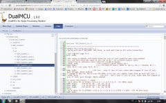
Quite interesting is that such "DualMCU" board is driven by software that has been published by T. Jaekel. The webpage dealing with 1) the configuration of the miniDSP MINI-FP, and 2) the configuration of the on-board Fractional-N Frequency Synthesizer is here : DualMCU: C:/Users/Torsten/Documents/Eclipse_WS2/Dual_MCU_32F767/BSP_DualMCU/src/BSP_DualMCU_i2c.c Source File
The software has a section named "BSP_DualMCU_i2c.h". This is in the form of a Board Support Package, only dealing with the I2C functions described above. It takes T. Jaekel, 648 lines of source code in C, for doing the required configurations through I2C.
See the attached .jpg.
Such is the drama of nowadays software engineering.
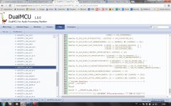
By the way, we still don't know about the STM32F7 Audio Clock Input, and the way T. Jaekel configured the SAI. He does through this : DualMCU: C:/Users/Torsten/Documents/Eclipse_WS2/Dual_MCU_32F767/HAL_Driver/Inc/stm32f7xx_hal_sai.h Source File
There are 903 lines of source code in C, this time originating from STM, as HAL (Hardware Abstraction Layer).
See the attached .jpg.
What do you think about this ?
Cheers,
Steph
T. Jaekel does.
This is in the context of his Lyrebird Audio Platform project.
T. Jaekel designed a board that he calls "DIGI-STM" acting as interconnect between a STM32F7 Discovery and a miniDSP DIGI-FP.
See the attached .pdf schematic.
The "DIGI-STM" board hosts a 24,5760 kHz quartz oscillator followed by a CS2000 Fractional-N Frequency Synthesizer configured by I2C. The 24,5760 kHz frequency corresponds to the 48 kHz related sampling frequencies. I guess T. Jaekel did this for getting a nearly infinite range of sampling frequencies. Instead, he could have relied on a second quartz oscillator, operating at 22,5792 kHz to be selected using a GPIO, for generating all 44.1 kHz related sampling frequencies.
Due to the presence of the CS2000 Fractional-N Frequency Synthesizer, such 512 x Fs clock may not exhibit an ideal 50% duty cycle. It may be required to divide it by two (in frequency) using a 74LVC74 D-Flip-Flop, before actually using it as MCLK for an ADC. Anyway, on the "DIGI-STM" schematic, we see that the output of the CS2000 goes straight to the MCLK_IN (pin 5) of the DIGI-FP. As you can see, it is the responsibility of the DIGI-FP user, to provide a MCLK exhibiting a decent quality. As soon as the MCLK is bad, the jitter will be bad.
Please note, the DIGI-FP gets configured also by a I2C.
This means that the "DIGI-STM" user must configure two devices using I2C : 1) the CS2000 sitting on the "DIGI-STM" board, and 2) the MINI-FP.
Piece of cake ?
Not really. See below.
Now, what's about the STM32F7 ?
First finding : to my surprise, according to the "DIGI-STM" schematic, the MCLK doesn't go to the STM32F7 Audio Clock Input.
Second finding : the digital audio gets hooked on the SAI of the STM32F7, in I2C protocol. The audio data that's coming from SDOUT (pin 3) of miniDSP MINI-FP gets routed to SAI1/B, for entering the STM32F7. The user needs to hardware-select SAI2/B or SAI1/A for collecting the processed audio that's coming from the STM32F7. The "DIGI-STM" board routes such processed audio, both to the on-board PCM5102 DAC, and to the SDIN (pin 4) of miniDSP DIGI-FP.
Later on, T. Jaekel designed a board that he calls "DualMCU" that's again acting as interconnect between a STM32F7 Discovery and a miniDSP DIGI-FP, but this time, such board embeds a STM32F7. The name "DualMCU" comes from the fact that one can daisy-chain a supplementary STMF7 board, exchanging audio data through the SAI.
Regarding the audio clocking, the "DualMCU" presentation sheet says about a "high-performance PLL used to support 48 as well as 44.1 KHz based audio sample rates" which means that again, we'll find a Fractional-N Frequency Synthesizer configured by I2C. This time, it can be a CS2300.
Quite interesting is that such "DualMCU" board is driven by software that has been published by T. Jaekel. The webpage dealing with 1) the configuration of the miniDSP MINI-FP, and 2) the configuration of the on-board Fractional-N Frequency Synthesizer is here : DualMCU: C:/Users/Torsten/Documents/Eclipse_WS2/Dual_MCU_32F767/BSP_DualMCU/src/BSP_DualMCU_i2c.c Source File
The software has a section named "BSP_DualMCU_i2c.h". This is in the form of a Board Support Package, only dealing with the I2C functions described above. It takes T. Jaekel, 648 lines of source code in C, for doing the required configurations through I2C.
See the attached .jpg.
Such is the drama of nowadays software engineering.
By the way, we still don't know about the STM32F7 Audio Clock Input, and the way T. Jaekel configured the SAI. He does through this : DualMCU: C:/Users/Torsten/Documents/Eclipse_WS2/Dual_MCU_32F767/HAL_Driver/Inc/stm32f7xx_hal_sai.h Source File
There are 903 lines of source code in C, this time originating from STM, as HAL (Hardware Abstraction Layer).
See the attached .jpg.
What do you think about this ?
Cheers,
Steph
Attachments
-
tjaekel Lyrebird DIGI-STM board connecting on miniDSP DIGI-FP (schematic).pdf352.2 KB · Views: 89
-
 tjaekel Lyrebird DualMCU is configuring miniDSP DIGI-FP using I2C (source code).jpg306.7 KB · Views: 414
 -
 tjaekel Lyrebird DualMCU is configuring the SAI using STM HAL (source code).jpg301.9 KB · Views: 396
Last edited:
Sorry for the typo, this is of course SAI in I2S protocol.Second finding : the digital audio gets hooked on the SAI of the STM32F7, in I2C protocol.
I kind of expect you are correct. The only reason I did a PIC32 version was as an intellectual exercise, and a challenge to myself to learn to code all the filters etc.
Generic micro's don't make great DSPs. In fact the PIC32 implementation only really worked when I made the compiler use the PIC32 DSP instructions.
That said, for the $5odd that a PIC32 costs, I think it is brilliant. As a challenge. (I guess I am showing my age - when I started electronics as a hobby there wasn't even a concept of "DSP" or "microcontroller")
They can be used as a DSP (Microchip market them as Digital Signal Controller), it depends how much signal processing you going to expect from it,you cannot expect it to do sample rates at 192KHz with 4 or 8-channels of simulations audio with a IIR/FIR (many taps) + EQ for each channel path, you can however make simple stuff, like delay correction, a "simple" EQ at maybe (48KHz sample rate) at 2-channels with reliable execution timings without choking it.
Besides a real DSP is just a special Processor or MCU with an Accumulator that offers SIMD execution / math instructions. like a SHARC DSP.
I have seen commercial sub-woofer plate products use 16-bit fixed point DSP with on board parametric EQ and LPF IIR Filters using only a PIC32 and that same MCU will even handle LCD and button I/O.
Last edited:
Hi,
I hope I will be able to provide quantifed answers, but those stm32F7 se to me very able.
I think that the USB part may be an issue for mey, but is not an issue: those things are good at receiving data and putting them in a buffer. It is just the correct control flow to be implemented.
About sampling rates and number of channels, testing will provide infos.
@Camelator: about ADAU, is there a product with ADAU, Asynch USB and good clock ?
Best regards,
JMF
Here is the system initialization code from the DualMCU webpage : DualMCU: C:/Users/Torsten/Documents/Eclipse_WS2/Dual_MCU_32F767/src/main.c Source File
It consists of a mix of code generated by STM32CubeMX, and code generated by T. Jaekel. Conditional compilation is used for selecting between overdrive (260 MHz) or no overdrive (212.336640 MHz).
It seems that the STM32F7 Audio Clock Input is not used.
Some things are unclear to me, like manually edited sections and values.
We need to revert to STMCubeMX, asking STMCubeMX to configure the chip, and see what code gets generated.
Steph
It consists of a mix of code generated by STM32CubeMX, and code generated by T. Jaekel. Conditional compilation is used for selecting between overdrive (260 MHz) or no overdrive (212.336640 MHz).
1
11 /* Includes ------------------------------------------------------------------*/
12 #include <string.h> //for memset, memcpy etc.
13
14 #include "stm32f7xx_hal.h"
15
16 /* USER CODE BEGIN Includes */
17 #include "BSP_DualMCU.h"
18
19 /* USER CODE END Includes */
20
25 /* Private variables ---------------------------------------------------------*/
26
30 DMA2D_HandleTypeDef hdma2d;
31
32 I2C_HandleTypeDef hi2c3;
33
34 SAI_HandleTypeDef hsai_BlockA1;
35 SAI_HandleTypeDef hsai_BlockB1;
36 SAI_HandleTypeDef hsai_BlockA2;
37 SAI_HandleTypeDef hsai_BlockB2;
38 DMA_HandleTypeDef hdma_sai1_a;
39 DMA_HandleTypeDef hdma_sai1_b;
40 DMA_HandleTypeDef hdma_sai2_a;
41 DMA_HandleTypeDef hdma_sai2_b;
42
43 SPI_HandleTypeDef hspi1;
44 SPI_HandleTypeDef hspi2;
45 DMA_HandleTypeDef hdma_spi2_rx;
46 DMA_HandleTypeDef hdma_spi2_tx;
47
48 TIM_HandleTypeDef htim3;
49 TIM_HandleTypeDef htim10;
50 TIM_HandleTypeDef htim11;
51
52 UART_HandleTypeDef huart6;
53 DMA_HandleTypeDef hdma_usart6_tx;
54 DMA_HandleTypeDef hdma_usart6_rx;
55
56 DMA_HandleTypeDef hdma_memtomem_dma2_stream0;
57
58 /* USER CODE BEGIN PV */
59 /* Private variables ---------------------------------------------------------*/
60
61 /* USER CODE END PV */
62
63 /* Private function prototypes -----------------------------------------------*/
64 void SystemClock_Config(void);
65
66 static void MX_GPIO_Init(void);
67 static void MX_DMA_Init(void);
68 #ifdef USE_DMA2D
69 static void MX_DMA2D_Init(void);
70 #endif
71 static void MX_I2C3_Init(void);
72 static void MX_SAI1_Init(void);
73 static void MX_SAI2_Init(void);
74 static void MX_SPI1_Init(void);
75 static void MX_SPI2_Init(void);
76 static void MX_TIM3_Init(void);
77 static void MX_TIM10_Init(void);
78 static void MX_TIM11_Init(void);
79 static void MX_USART6_UART_Init(void);
80
81 /* USER CODE BEGIN PFP */
82 /* Private function prototypes -----------------------------------------------*/
83
84 /* USER CODE END PFP */
85
86 /* USER CODE BEGIN 0 */
87
88 /* USER CODE END 0 */
89
96 int main(void)
97 {
98 /* USER CODE BEGIN 1 */
99
100 /* USER CODE END 1 */
101
102 /* Enable I-Cache-------------------------------------------------------------*/
103 SCB_EnableICache();
104
105 /* Enable D-Cache-------------------------------------------------------------*/
106 SCB_EnableDCache();
107
108 /* MCU Configuration----------------------------------------------------------*/
109
110 /* Reset of all peripherals, Initializes the Flash interface and the Systick */
111 HAL_Init();
112
113 /* Initialize all configured peripherals */
114 MX_GPIO_Init(); //GPIO first - needed for PLL chip (I2C must be later)
115 MX_I2C3_Init(); //init I2C
116
117 SRC_I2C_Configure(); //configure PLL chip
118
119 /* Configure the system clock after PLL should have locked */
120 SystemClock_Config();
121 SystemCoreClockUpdate();
122
123 MX_I2C3_Init(); //init I2C again after PLL clock changed
124 MX_DMA_Init(); //not really used
125 #ifdef USE_DMA2D
126 MX_DMA2D_Init();
127 #endif
128 MX_SAI1_Init();
129 MX_SAI2_Init();
130 MX_SPI1_Init();
131 MX_SPI2_Init();
132 MX_TIM3_Init();
133 MX_TIM10_Init();
134 MX_TIM11_Init();
135 MX_USART6_UART_Init();
136
137 /* USER CODE BEGIN 2 */
138 BSP_LED_On(0);
139
140 //initialize TIM for CPU load measurement
141 MEASURE_Init();
142
143 /* configure audio system */
144 SYSCFG_ConfigureAll();
145
146 /* USER CODE END 2 */
147
148 /* Infinite loop */
149 /* USER CODE BEGIN WHILE */
150 while (1)
151 {
152 HAL_Delay(1);
153
154 /* USER CODE END WHILE */
155 task_main();
156
157 /*
158 * if it returns - there was an error in one of the tasks, breaking the loop
159 * --> we should assume to restart all here then
160 */
161
162 /* USER CODE BEGIN 3 */
163
164 }
165 /* USER CODE END 3 */
166
167 }
168
171 #if 0
172
178 void SystemClock_Config(void)
179 {
180 RCC_OscInitTypeDef RCC_OscInitStruct;
181 RCC_ClkInitTypeDef RCC_ClkInitStruct;
182 RCC_PeriphCLKInitTypeDef PeriphClkInitStruct;
183
184 __PWR_CLK_ENABLE();
185
186 __HAL_PWR_VOLTAGESCALING_CONFIG(PWR_REGULATOR_VOLTAGE_SCALE1);
187
188 RCC_OscInitStruct.OscillatorType = /*RCC_OSCILLATORTYPE_HSI|*/RCC_OSCILLATORTYPE_HSE;
189 RCC_OscInitStruct.HSEState = RCC_HSE_ON; //RCC_HSE_BYPASS; //RCC_HSE_ON;
190 RCC_OscInitStruct.HSIState = RCC_HSE_OFF; //RCC_HSI_ON; //RCC_HSE_OFF;
191 RCC_OscInitStruct.HSICalibrationValue = 16;
192 RCC_OscInitStruct.PLL.PLLState = RCC_PLL_ON;
193 RCC_OscInitStruct.PLL.PLLSource = RCC_PLLSOURCE_HSE;
194 //25, 432, 9 -> 212.336640 MHz
195 RCC_OscInitStruct.PLL.PLLM = 25;
196 RCC_OscInitStruct.PLL.PLLN = 432;
197 RCC_OscInitStruct.PLL.PLLP = RCC_PLLP_DIV2;
198 RCC_OscInitStruct.PLL.PLLQ = 9;
199 HAL_RCC_OscConfig(&RCC_OscInitStruct);
200
201 HAL_PWREx_ActivateOverDrive();
202
203 RCC_ClkInitStruct.ClockType = RCC_CLOCKTYPE_HCLK|RCC_CLOCKTYPE_SYSCLK
204 |RCC_CLOCKTYPE_PCLK1|RCC_CLOCKTYPE_PCLK2;
205 RCC_ClkInitStruct.SYSCLKSource = RCC_SYSCLKSOURCE_PLLCLK;
206 RCC_ClkInitStruct.AHBCLKDivider = RCC_SYSCLK_DIV1;
207 RCC_ClkInitStruct.APB1CLKDivider = RCC_HCLK_DIV4;
208 RCC_ClkInitStruct.APB2CLKDivider = RCC_HCLK_DIV2;
209
210 HAL_RCC_ClockConfig(&RCC_ClkInitStruct, FLASH_LATENCY_6);
211
212 PeriphClkInitStruct.PeriphClockSelection = RCC_PERIPHCLK_USART6|RCC_PERIPHCLK_SAI1
213 |RCC_PERIPHCLK_SAI2|RCC_PERIPHCLK_I2C3;
214 PeriphClkInitStruct.PLLSAI.PLLSAIN = 192; //50;
215 PeriphClkInitStruct.PLLSAI.PLLSAIR = 2;
216 PeriphClkInitStruct.PLLSAI.PLLSAIQ = 2;
217 PeriphClkInitStruct.PLLSAI.PLLSAIP = RCC_PLLSAIP_DIV2;
218 PeriphClkInitStruct.PLLSAIDivQ = 1;
219 PeriphClkInitStruct.PLLSAIDivR = RCC_PLLSAIDIVR_2;
220 PeriphClkInitStruct.Sai1ClockSelection = RCC_SAI1CLKSOURCE_PLLSAI;
221 PeriphClkInitStruct.Sai2ClockSelection = RCC_SAI2CLKSOURCE_PLLSAI;
222 PeriphClkInitStruct.Usart6ClockSelection = RCC_USART6CLKSOURCE_PCLK2;
223 PeriphClkInitStruct.I2c3ClockSelection = RCC_I2C3CLKSOURCE_PCLK1;
224 HAL_RCCEx_PeriphCLKConfig(&PeriphClkInitStruct);
225
226 HAL_RCC_MCOConfig(RCC_MCO1, RCC_MCO1SOURCE_HSI, RCC_MCODIV_1);
227
228 HAL_SYSTICK_Config(HAL_RCC_GetHCLKFreq()/1000);
229
230 HAL_SYSTICK_CLKSourceConfig(SYSTICK_CLKSOURCE_HCLK);
231
232 /* SysTick_IRQn interrupt configuration */
233 HAL_NVIC_SetPriority(SysTick_IRQn, 0, 0);
234 }
235 #else
236
242 void SystemClock_Config(void)
243 {
244 RCC_OscInitTypeDef RCC_OscInitStruct;
245 RCC_ClkInitTypeDef RCC_ClkInitStruct;
246 RCC_PeriphCLKInitTypeDef PeriphClkInitStruct;
247
248 __PWR_CLK_ENABLE();
249
250 __HAL_PWR_VOLTAGESCALING_CONFIG(PWR_REGULATOR_VOLTAGE_SCALE1);
251
252 RCC_OscInitStruct.OscillatorType = RCC_OSCILLATORTYPE_HSI;
253 RCC_OscInitStruct.HSIState = RCC_HSI_ON;
254 RCC_OscInitStruct.HSICalibrationValue = 16;
255 RCC_OscInitStruct.PLL.PLLState = RCC_PLL_ON;
256 RCC_OscInitStruct.PLL.PLLSource = RCC_PLLSOURCE_HSI;
257 RCC_OscInitStruct.PLL.PLLM = 8;
258 //Over-clocking! 260 MHz is max. possible
259 #ifdef OVERCLOCKING
260 RCC_OscInitStruct.PLL.PLLN = 260; //nominal 216, max. 260
261 #else
262 RCC_OscInitStruct.PLL.PLLN = 216; //nominal clock
263 #endif
264 RCC_OscInitStruct.PLL.PLLP = RCC_PLLP_DIV2;
265 RCC_OscInitStruct.PLL.PLLQ = 2;
266 HAL_RCC_OscConfig(&RCC_OscInitStruct);
267
268 HAL_PWREx_ActivateOverDrive();
269
270 RCC_ClkInitStruct.ClockType = RCC_CLOCKTYPE_HCLK|RCC_CLOCKTYPE_SYSCLK
271 |RCC_CLOCKTYPE_PCLK1|RCC_CLOCKTYPE_PCLK2;
272 RCC_ClkInitStruct.SYSCLKSource = RCC_SYSCLKSOURCE_PLLCLK;
273 RCC_ClkInitStruct.AHBCLKDivider = RCC_SYSCLK_DIV1;
274 RCC_ClkInitStruct.APB1CLKDivider = RCC_HCLK_DIV4;
275 RCC_ClkInitStruct.APB2CLKDivider = RCC_HCLK_DIV2;
276 HAL_RCC_ClockConfig(&RCC_ClkInitStruct, FLASH_LATENCY_7);
277
278 PeriphClkInitStruct.PeriphClockSelection = RCC_PERIPHCLK_USART6|RCC_PERIPHCLK_SAI1
279 |RCC_PERIPHCLK_SAI2|RCC_PERIPHCLK_I2C3;
280 PeriphClkInitStruct.PLLSAI.PLLSAIN = 50;
281 PeriphClkInitStruct.PLLSAI.PLLSAIR = 2;
282 PeriphClkInitStruct.PLLSAI.PLLSAIQ = 2;
283 PeriphClkInitStruct.PLLSAI.PLLSAIP = RCC_PLLSAIP_DIV2;
284 PeriphClkInitStruct.PLLSAIDivQ = 1;
285 PeriphClkInitStruct.PLLSAIDivR = RCC_PLLSAIDIVR_2;
286 PeriphClkInitStruct.Sai1ClockSelection = RCC_SAI1CLKSOURCE_PLLSAI;
287 PeriphClkInitStruct.Sai2ClockSelection = RCC_SAI2CLKSOURCE_PLLSAI;
288 PeriphClkInitStruct.Usart6ClockSelection = RCC_USART6CLKSOURCE_PCLK2;
289 PeriphClkInitStruct.I2c3ClockSelection = RCC_I2C3CLKSOURCE_PCLK1;
290 HAL_RCCEx_PeriphCLKConfig(&PeriphClkInitStruct);
291
292 HAL_RCC_MCOConfig(RCC_MCO1, RCC_MCO1SOURCE_HSI, RCC_MCODIV_1);
293
294 HAL_SYSTICK_Config(HAL_RCC_GetHCLKFreq()/1000);
295
296 HAL_SYSTICK_CLKSourceConfig(SYSTICK_CLKSOURCE_HCLK);
297
298 /* SysTick_IRQn interrupt configuration */
299 HAL_NVIC_SetPriority(SysTick_IRQn, 0, 0);
300 }
301 #endif
302
303 #ifdef USE_DMA2D
304
309 static void MX_DMA2D_Init(void)
310 {
314 hdma2d.Instance = DMA2D;
315 hdma2d.Init.Mode = DMA2D_M2M;
316 hdma2d.Init.ColorMode = DMA2D_ARGB8888;
317 hdma2d.Init.OutputOffset = 1; //2 pixels per line, jump to next half
318 hdma2d.LayerCfg[1].InputOffset = 0;
319 hdma2d.LayerCfg[1].InputColorMode = CM_ARGB8888;
320 hdma2d.LayerCfg[1].AlphaMode = DMA2D_NO_MODIF_ALPHA;
321 hdma2d.LayerCfg[1].InputAlpha = 0x0;
322 HAL_DMA2D_Init(&hdma2d);
323
324 HAL_DMA2D_ConfigLayer(&hdma2d, 1); //foreground
325 }
326 #endif
327
329 static void MX_I2C3_Init(void)
330 {
331 hi2c3.Instance = I2C3;
332 hi2c3.Init.Timing = 0x40202A3F; //x1060679A;
333 hi2c3.Init.OwnAddress1 = 0;
334 hi2c3.Init.AddressingMode = I2C_ADDRESSINGMODE_7BIT;
335 hi2c3.Init.DualAddressMode = I2C_DUALADDRESS_DISABLE;
336 hi2c3.Init.OwnAddress2 = 0;
337 hi2c3.Init.OwnAddress2Masks = I2C_OA2_NOMASK;
338 hi2c3.Init.GeneralCallMode = I2C_GENERALCALL_DISABLE;
339 hi2c3.Init.NoStretchMode = I2C_NOSTRETCH_DISABLE;
340 HAL_I2C_Init(&hi2c3);
341
343 HAL_I2CEx_AnalogFilter_Config(&hi2c3, I2C_ANALOGFILTER_ENABLE);
344 }
345
347 static void MX_SAI1_Init(void)
348 {
349 hsai_BlockA1.Instance = SAI1_Block_A;
350 hsai_BlockA1.Init.AudioMode = SAI_MODESLAVE_RX;
351 hsai_BlockA1.Init.Synchro = SAI_ASYNCHRONOUS;
352 hsai_BlockA1.Init.OutputDrive = SAI_OUTPUTDRIVE_ENABLED;
353 hsai_BlockA1.Init.FIFOThreshold = SAI_FIFOTHRESHOLD_1QF;
354 hsai_BlockA1.Init.SynchroExt = SAI_SYNCEXT_OUTBLOCKA_ENABLE; //SAI_SYNCEXT_DISABLE;
355 hsai_BlockA1.Init.MonoStereoMode = SAI_STEREOMODE;
356 hsai_BlockA1.Init.CompandingMode = SAI_NOCOMPANDING;
357 hsai_BlockA1.Init.TriState = SAI_OUTPUT_NOTRELEASED;
358 HAL_SAI_InitProtocol(&hsai_BlockA1, SAI_I2S_STANDARD, SAI_PROTOCOL_DATASIZE_32BIT, 2);
359
360 hsai_BlockB1.Instance = SAI1_Block_B;
361 hsai_BlockB1.Init.AudioMode = SAI_MODESLAVE_TX;
362 hsai_BlockB1.Init.Synchro = SAI_SYNCHRONOUS;
363 hsai_BlockB1.Init.OutputDrive = SAI_OUTPUTDRIVE_ENABLED;
364 hsai_BlockB1.Init.FIFOThreshold = SAI_FIFOTHRESHOLD_1QF;
365 hsai_BlockB1.Init.SynchroExt = SAI_SYNCEXT_DISABLE;
366 hsai_BlockB1.Init.MonoStereoMode = SAI_STEREOMODE;
367 hsai_BlockB1.Init.CompandingMode = SAI_NOCOMPANDING;
368 hsai_BlockB1.Init.TriState = SAI_OUTPUT_NOTRELEASED;
369 HAL_SAI_InitProtocol(&hsai_BlockB1, SAI_I2S_STANDARD, SAI_PROTOCOL_DATASIZE_32BIT, 2);
370 }
371
373 static void MX_SAI2_Init(void)
374 {
375 hsai_BlockA2.Instance = SAI2_Block_A;
376 hsai_BlockA2.Init.AudioMode = SAI_MODESLAVE_RX;
377 hsai_BlockA2.Init.Synchro = SAI_ASYNCHRONOUS;
378 hsai_BlockA2.Init.OutputDrive = SAI_OUTPUTDRIVE_ENABLED;
379 hsai_BlockA2.Init.FIFOThreshold = SAI_FIFOTHRESHOLD_1QF;
380 hsai_BlockA2.Init.SynchroExt = SAI_SYNCEXT_OUTBLOCKB_ENABLE; //SAI_SYNCEXT_DISABLE;
381 hsai_BlockA2.Init.MonoStereoMode = SAI_STEREOMODE;
382 hsai_BlockA2.Init.CompandingMode = SAI_NOCOMPANDING;
383 hsai_BlockA2.Init.TriState = SAI_OUTPUT_NOTRELEASED;
384 HAL_SAI_InitProtocol(&hsai_BlockA2, SAI_I2S_STANDARD, SAI_PROTOCOL_DATASIZE_32BIT, 2);
385
386 hsai_BlockB2.Instance = SAI2_Block_B;
387 hsai_BlockB2.Init.AudioMode = SAI_MODESLAVE_TX;
388 hsai_BlockB2.Init.Synchro = SAI_SYNCHRONOUS;
389 hsai_BlockB2.Init.OutputDrive = SAI_OUTPUTDRIVE_ENABLED;
390 hsai_BlockB2.Init.FIFOThreshold = SAI_FIFOTHRESHOLD_1QF;
391 hsai_BlockB2.Init.SynchroExt = SAI_SYNCEXT_DISABLE;
392 hsai_BlockB2.Init.MonoStereoMode = SAI_STEREOMODE;
393 hsai_BlockB2.Init.CompandingMode = SAI_NOCOMPANDING;
394 hsai_BlockB2.Init.TriState = SAI_OUTPUT_NOTRELEASED;
395 HAL_SAI_InitProtocol(&hsai_BlockB2, SAI_I2S_STANDARD, SAI_PROTOCOL_DATASIZE_32BIT, 2);
396 }
397
399 static void MX_SPI1_Init(void)
400 {
401 hspi1.Instance = SPI1;
402 hspi1.Init.Mode = SPI_MODE_MASTER;
403 hspi1.Init.Direction = SPI_DIRECTION_2LINES;
404 hspi1.Init.DataSize = SPI_DATASIZE_8BIT;
405 hspi1.Init.CLKPolarity = SPI_POLARITY_LOW;
406 hspi1.Init.CLKPhase = SPI_PHASE_1EDGE;
407 hspi1.Init.NSS = SPI_NSS_HARD_OUTPUT;
408 hspi1.Init.BaudRatePrescaler = SPI_BAUDRATEPRESCALER_8;
409 hspi1.Init.FirstBit = SPI_FIRSTBIT_MSB;
410 hspi1.Init.TIMode = SPI_TIMODE_DISABLED;
411 hspi1.Init.CRCCalculation = SPI_CRCCALCULATION_DISABLED;
412 hspi1.Init.CRCPolynomial = 7;
413 hspi1.Init.CRCLength = SPI_CRC_LENGTH_DATASIZE;
414 hspi1.Init.NSSPMode = SPI_NSS_PULSE_ENABLED;
415 HAL_SPI_Init(&hspi1);
416 }
417
419 static void MX_SPI2_Init(void)
420 {
421 hspi2.Instance = SPI2;
422 hspi2.Init.Mode = SPI_MODE_SLAVE;
423 hspi2.Init.Direction = SPI_DIRECTION_2LINES;
424 hspi2.Init.DataSize = SPI_DATASIZE_16BIT;
425 hspi2.Init.CLKPolarity = SPI_POLARITY_LOW;
426 hspi2.Init.CLKPhase = SPI_PHASE_1EDGE;
427 hspi2.Init.NSS = SPI_NSS_HARD_INPUT; //SPI_NSS_SOFT; //SPI_NSS_HARD_INPUT;
428 hspi2.Init.FirstBit = SPI_FIRSTBIT_MSB;
429 hspi2.Init.TIMode = SPI_TIMODE_DISABLED;
430 hspi2.Init.CRCCalculation = SPI_CRCCALCULATION_DISABLED;
431 hspi2.Init.CRCPolynomial = 7;
432 hspi2.Init.CRCLength = SPI_CRC_LENGTH_DATASIZE;
433 hspi2.Init.NSSPMode = SPI_NSS_PULSE_DISABLED;
434 HAL_SPI_Init(&hspi2);
435 }
436
438 static void MX_TIM3_Init(void)
439 {
440 TIM_ClockConfigTypeDef sClockSourceConfig;
441 TIM_SlaveConfigTypeDef sSlaveConfig;
442 TIM_MasterConfigTypeDef sMasterConfig;
443 TIM_OC_InitTypeDef sConfigOC;
444
445 htim3.Instance = TIM3;
446 htim3.Init.Prescaler = 0;
447 htim3.Init.CounterMode = TIM_COUNTERMODE_UP;
448 htim3.Init.Period = 0;
449 htim3.Init.ClockDivision = TIM_CLOCKDIVISION_DIV1;
450 HAL_TIM_Base_Init(&htim3);
451
452 sClockSourceConfig.ClockSource = TIM_CLOCKSOURCE_INTERNAL;
453 HAL_TIM_ConfigClockSource(&htim3, &sClockSourceConfig);
454
455 HAL_TIM_PWM_Init(&htim3);
456
457 sSlaveConfig.SlaveMode = TIM_SLAVEMODE_GATED;
458 sSlaveConfig.InputTrigger = TIM_TS_ITR0;
459 HAL_TIM_SlaveConfigSynchronization(&htim3, &sSlaveConfig);
460
461 sMasterConfig.MasterOutputTrigger = TIM_TRGO_RESET;
462 sMasterConfig.MasterSlaveMode = TIM_MASTERSLAVEMODE_DISABLE;
463 HAL_TIMEx_MasterConfigSynchronization(&htim3, &sMasterConfig);
464
465 sConfigOC.OCMode = TIM_OCMODE_PWM1;
466 sConfigOC.Pulse = 0;
467 sConfigOC.OCPolarity = TIM_OCPOLARITY_HIGH;
468 sConfigOC.OCFastMode = TIM_OCFAST_DISABLE;
469 HAL_TIM_PWM_ConfigChannel(&htim3, &sConfigOC, TIM_CHANNEL_3);
470 }
471
473 static void MX_TIM10_Init(void)
474 {
475 TIM_IC_InitTypeDef sConfigIC;
476
477 htim10.Instance = TIM10;
478 htim10.Init.Prescaler = 0;
479 htim10.Init.CounterMode = TIM_COUNTERMODE_UP;
480 htim10.Init.Period = 0;
481 htim10.Init.ClockDivision = TIM_CLOCKDIVISION_DIV1;
482 HAL_TIM_Base_Init(&htim10);
483
484 HAL_TIM_IC_Init(&htim10);
485
486 sConfigIC.ICPolarity = TIM_INPUTCHANNELPOLARITY_RISING;
487 sConfigIC.ICSelection = TIM_ICSELECTION_DIRECTTI;
488 sConfigIC.ICPrescaler = TIM_ICPSC_DIV1;
489 sConfigIC.ICFilter = 0;
490 HAL_TIM_IC_ConfigChannel(&htim10, &sConfigIC, TIM_CHANNEL_1);
491 }
492
494 static void MX_TIM11_Init(void)
495 {
496 TIM_IC_InitTypeDef sConfigIC;
497
498 htim11.Instance = TIM11;
499 htim11.Init.Prescaler = 0;
500 htim11.Init.CounterMode = TIM_COUNTERMODE_UP;
501 htim11.Init.Period = 0;
502 htim11.Init.ClockDivision = TIM_CLOCKDIVISION_DIV1;
503 HAL_TIM_Base_Init(&htim11);
504
505 HAL_TIM_IC_Init(&htim11);
506
507 sConfigIC.ICPolarity = TIM_INPUTCHANNELPOLARITY_RISING;
508 sConfigIC.ICSelection = TIM_ICSELECTION_DIRECTTI;
509 sConfigIC.ICPrescaler = TIM_ICPSC_DIV1;
510 sConfigIC.ICFilter = 0;
511 HAL_TIM_IC_ConfigChannel(&htim11, &sConfigIC, TIM_CHANNEL_1);
512 }
513
515 static void MX_USART6_UART_Init(void)
516 {
517 huart6.Instance = USART6;
518 huart6.Init.BaudRate = UART_BAUDRATE;
519 huart6.Init.WordLength = UART_WORDLENGTH_8B;
520 huart6.Init.StopBits = UART_STOPBITS_1;
521 huart6.Init.Parity = UART_PARITY_NONE;
522 huart6.Init.Mode = UART_MODE_TX_RX;
523 huart6.Init.HwFlowCtl = UART_HWCONTROL_NONE;
524 huart6.Init.OverSampling = UART_OVERSAMPLING_16;
525 huart6.Init.OneBitSampling = UART_ONEBIT_SAMPLING_DISABLED;
526 huart6.AdvancedInit.AdvFeatureInit = UART_ADVFEATURE_NO_INIT;
527 HAL_UART_Init(&huart6);
528 }
529
535 static void MX_DMA_Init(void)
536 {
537 /* DMA controller clock enable */
538 __HAL_RCC_DMA2_CLK_ENABLE();
539 __HAL_RCC_DMA1_CLK_ENABLE();
540
541 /* Configure DMA request hdma_memtomem_dma2_stream0 on DMA2_Stream0 */
542 hdma_memtomem_dma2_stream0.Instance = DMA2_Stream0;
543 hdma_memtomem_dma2_stream0.Init.Channel = DMA_CHANNEL_0;
544 hdma_memtomem_dma2_stream0.Init.Direction = DMA_MEMORY_TO_MEMORY;
545 hdma_memtomem_dma2_stream0.Init.PeriphInc = DMA_PINC_ENABLE;
546 hdma_memtomem_dma2_stream0.Init.MemInc = DMA_MINC_ENABLE;
547 hdma_memtomem_dma2_stream0.Init.PeriphDataAlignment = DMA_PDATAALIGN_WORD;
548 hdma_memtomem_dma2_stream0.Init.MemDataAlignment = DMA_MDATAALIGN_WORD;
549 hdma_memtomem_dma2_stream0.Init.Mode = DMA_NORMAL;
550 hdma_memtomem_dma2_stream0.Init.Priority = DMA_PRIORITY_MEDIUM;
551 hdma_memtomem_dma2_stream0.Init.FIFOMode = DMA_FIFOMODE_ENABLE;
552 hdma_memtomem_dma2_stream0.Init.FIFOThreshold = DMA_FIFO_THRESHOLD_FULL;
553 hdma_memtomem_dma2_stream0.Init.MemBurst = DMA_MBURST_INC4;
554 hdma_memtomem_dma2_stream0.Init.PeriphBurst = DMA_PBURST_INC4;
555 HAL_DMA_Init(&hdma_memtomem_dma2_stream0);
556
557 /* DMA interrupt init */
558 HAL_NVIC_SetPriority(DMA1_Stream3_IRQn, 0, 0);
559 HAL_NVIC_EnableIRQ(DMA1_Stream3_IRQn);
560 HAL_NVIC_SetPriority(DMA1_Stream4_IRQn, 0, 0);
561 HAL_NVIC_EnableIRQ(DMA1_Stream4_IRQn);
562 HAL_NVIC_SetPriority(DMA2_Stream1_IRQn, 0, 0);
563 HAL_NVIC_EnableIRQ(DMA2_Stream1_IRQn);
564 HAL_NVIC_SetPriority(DMA2_Stream2_IRQn, 0, 0);
565 HAL_NVIC_EnableIRQ(DMA2_Stream2_IRQn);
566 HAL_NVIC_SetPriority(DMA2_Stream4_IRQn, 0, 0);
567 HAL_NVIC_EnableIRQ(DMA2_Stream4_IRQn);
568 HAL_NVIC_SetPriority(DMA2_Stream5_IRQn, 0, 0);
569 HAL_NVIC_EnableIRQ(DMA2_Stream5_IRQn);
570 HAL_NVIC_SetPriority(DMA2_Stream6_IRQn, 0, 0);
571 HAL_NVIC_EnableIRQ(DMA2_Stream6_IRQn);
572 HAL_NVIC_SetPriority(DMA2_Stream7_IRQn, 0, 0);
573 HAL_NVIC_EnableIRQ(DMA2_Stream7_IRQn);
574 }
575
583 static void MX_GPIO_Init(void)
584 {
585 GPIO_InitTypeDef GPIO_InitStruct;
586
587 /* GPIO Ports Clock Enable */
588 __GPIOE_CLK_ENABLE();
589 __GPIOH_CLK_ENABLE();
590 __GPIOC_CLK_ENABLE();
591 __GPIOA_CLK_ENABLE();
592 __GPIOB_CLK_ENABLE();
593 __GPIOD_CLK_ENABLE();
594
595 #if 0
596 /*Configure GPIO pins : PC2 PC3 PC10 PC11 */
597 GPIO_InitStruct.Pin = GPIO_PIN_2|GPIO_PIN_3|GPIO_PIN_10|GPIO_PIN_11;
598 GPIO_InitStruct.Mode = GPIO_MODE_INPUT;
599 GPIO_InitStruct.Pull = GPIO_NOPULL;
600 HAL_GPIO_Init(GPIOC, &GPIO_InitStruct);
601 #else
602 //if DualMCU is master - PC10, PC11 is output for WC Select
603 /*Configure GPIO pins : PC2 PC3 */
604 GPIO_InitStruct.Pin = GPIO_PIN_2|GPIO_PIN_3;
605 GPIO_InitStruct.Mode = GPIO_MODE_INPUT;
606 GPIO_InitStruct.Pull = GPIO_NOPULL;
607 HAL_GPIO_Init(GPIOC, &GPIO_InitStruct);
608
609 /*Configure GPIO pins : PC10 PC11 */
610 GPIO_InitStruct.Pin = GPIO_PIN_10|GPIO_PIN_11;
611 GPIO_InitStruct.Mode = GPIO_MODE_OUTPUT_PP;
612 GPIO_InitStruct.Pull = GPIO_NOPULL;
613 HAL_GPIO_Init(GPIOC, &GPIO_InitStruct);
614
615 //set a default WC - here 0 as "No WC"
616 //ATT: if we use 3 - we select WC BNC and do not get 216 MHz SysClock if open
617 //because there is noise!
618 HAL_GPIO_WritePin(GPIOC, GPIO_PIN_10, GPIO_PIN_RESET);
619 HAL_GPIO_WritePin(GPIOC, GPIO_PIN_11, GPIO_PIN_RESET);
620 #endif
621
622 /*Configure GPIO pins : PA2 PA3 */
623 GPIO_InitStruct.Pin = GPIO_PIN_2|GPIO_PIN_3;
624 GPIO_InitStruct.Mode = GPIO_MODE_INPUT;
625 GPIO_InitStruct.Pull = GPIO_NOPULL;
626 HAL_GPIO_Init(GPIOA, &GPIO_InitStruct);
627
628 /*Configure GPIO pins : PE0 PE1 */
629 GPIO_InitStruct.Pin = GPIO_PIN_0|GPIO_PIN_1;
630 GPIO_InitStruct.Mode = GPIO_MODE_OUTPUT_PP;
631 GPIO_InitStruct.Pull = GPIO_NOPULL;
632 GPIO_InitStruct.Speed = GPIO_SPEED_LOW;
633 HAL_GPIO_Init(GPIOE, &GPIO_InitStruct);
634 }
635
636 /* USER CODE BEGIN 4 */
637
638 /* USER CODE END 4 */
639
644 #ifdef USE_FULL_ASSERT
645
652 void assert_failed(uint8_t* file, uint32_t line)
653 {
654 /* USER CODE BEGIN 6 */
655 /* User can add his own implementation to report the file name and line number,
656 ex: printf("Wrong parameters value: file %s on line %d\r\n", file, line) */
657 /* USER CODE END 6 */
658
659 }
660 #endif
661
670 /************************ (C) COPYRIGHT STMicroelectronics *****END OF FILE****/
It seems that the STM32F7 Audio Clock Input is not used.
Some things are unclear to me, like manually edited sections and values.
We need to revert to STMCubeMX, asking STMCubeMX to configure the chip, and see what code gets generated.
Steph
I propose a clean sheet start.
There must be a 25 MHz quartz on HSE. One cannot rely on the 16 MHz internal RC oscillator, then ask PLLM to divide it by 16. Doing so, STM32CubeMX turrns the "PLL Source Mux" red, warning that "PLL Mux should have HSE as input". Can somebody tell why ? By the way, one could have relied on a 16 MHz quartz on HSE, divided by 16 in PLLM.
Anyway, we get a 216 MHz SYSCLK. No overdrive thus.
The AHB prescaler is set to 1. We get a 216 MHz HCLK.
The APB1 prescaler is set to 8. We get a 27 MHz PCLK1 (max is 50 MHz).
The APB2 prescaler is set to 4. We get a 54 MHz PCLK1 (max is 100 MHz).
Please note, in tjaekel DualMMU, APB1 prescaler was set to 4, and APB2 prescaler was set to 2, meaning their frequencies were exceeding the max.
PLLSAI1 gets in charge of clocking the SAI1 and SAI2, clocked by PLLSAIQ.
N = 192
P = 2
Q = 2
R = 2
PLLSAIQ is 96 MHz.
Can somebody tell the purpose of such clock in the SAI ?
The SAI get configured same way as tjaekel DualMCU.
They are all SLAVES.
Which means that they receive both the 48 kHz frame sync, and the bit clock.
Am I right ?
By the way, I am not sure about the SAI "SynchroExt" parameters.
Can somebody tell ?
Anyway, here is the code that's generated by STM32CubeMX.
I don't like the way STM32CubeMX interleaves user code with automatically generated code. There is an option in the STM32CubeMX settings, about keeping the user code. I don't know how this can work.
I am attaching the STMCubeMX .ioc file wrapped into a .zip so you can reverse-engineer the clean sheet start proposition.
I added USB support, just in case, as future discussion base.
Regards,
Steph
There must be a 25 MHz quartz on HSE. One cannot rely on the 16 MHz internal RC oscillator, then ask PLLM to divide it by 16. Doing so, STM32CubeMX turrns the "PLL Source Mux" red, warning that "PLL Mux should have HSE as input". Can somebody tell why ? By the way, one could have relied on a 16 MHz quartz on HSE, divided by 16 in PLLM.
Anyway, we get a 216 MHz SYSCLK. No overdrive thus.
The AHB prescaler is set to 1. We get a 216 MHz HCLK.
The APB1 prescaler is set to 8. We get a 27 MHz PCLK1 (max is 50 MHz).
The APB2 prescaler is set to 4. We get a 54 MHz PCLK1 (max is 100 MHz).
Please note, in tjaekel DualMMU, APB1 prescaler was set to 4, and APB2 prescaler was set to 2, meaning their frequencies were exceeding the max.
PLLSAI1 gets in charge of clocking the SAI1 and SAI2, clocked by PLLSAIQ.
N = 192
P = 2
Q = 2
R = 2
PLLSAIQ is 96 MHz.
Can somebody tell the purpose of such clock in the SAI ?
The SAI get configured same way as tjaekel DualMCU.
They are all SLAVES.
Which means that they receive both the 48 kHz frame sync, and the bit clock.
Am I right ?
By the way, I am not sure about the SAI "SynchroExt" parameters.
Can somebody tell ?
Anyway, here is the code that's generated by STM32CubeMX.
/* Includes ------------------------------------------------------------------*/
#include "stm32f7xx_hal.h"
/* USER CODE BEGIN Includes */
/* USER CODE END Includes */
/* Private variables ---------------------------------------------------------*/
SAI_HandleTypeDef hsai_BlockA1;
SAI_HandleTypeDef hsai_BlockB1;
SAI_HandleTypeDef hsai_BlockA2;
SAI_HandleTypeDef hsai_BlockB2;
PCD_HandleTypeDef hpcd_USB_OTG_HS;
/* USER CODE BEGIN PV */
/* Private variables ---------------------------------------------------------*/
/* USER CODE END PV */
/* Private function prototypes -----------------------------------------------*/
void SystemClock_Config(void);
static void MX_GPIO_Init(void);
static void MX_SAI1_Init(void);
static void MX_SAI2_Init(void);
static void MX_USB_OTG_HS_PCD_Init(void);
/* USER CODE BEGIN PFP */
/* Private function prototypes -----------------------------------------------*/
/* USER CODE END PFP */
/* USER CODE BEGIN 0 */
/* USER CODE END 0 */
int main(void)
{
/* USER CODE BEGIN 1 */
/* USER CODE END 1 */
/* MCU Configuration----------------------------------------------------------*/
/* Reset of all peripherals, Initializes the Flash interface and the Systick. */
HAL_Init();
/* Configure the system clock */
SystemClock_Config();
/* Initialize all configured peripherals */
MX_GPIO_Init();
MX_SAI1_Init();
MX_SAI2_Init();
MX_USB_OTG_HS_PCD_Init();
/* USER CODE BEGIN 2 */
/* USER CODE END 2 */
/* Infinite loop */
/* USER CODE BEGIN WHILE */
while (1)
{
/* USER CODE END WHILE */
/* USER CODE BEGIN 3 */
}
/* USER CODE END 3 */
}
/** System Clock Configuration
*/
void SystemClock_Config(void)
{
RCC_OscInitTypeDef RCC_OscInitStruct;
RCC_ClkInitTypeDef RCC_ClkInitStruct;
RCC_PeriphCLKInitTypeDef PeriphClkInitStruct;
__PWR_CLK_ENABLE();
__HAL_PWR_VOLTAGESCALING_CONFIG(PWR_REGULATOR_VOLTAGE_SCALE1);
RCC_OscInitStruct.OscillatorType = RCC_OSCILLATORTYPE_HSE;
RCC_OscInitStruct.HSEState = RCC_HSE_ON;
RCC_OscInitStruct.PLL.PLLState = RCC_PLL_ON;
RCC_OscInitStruct.PLL.PLLSource = RCC_PLLSOURCE_HSE;
RCC_OscInitStruct.PLL.PLLM = 25;
RCC_OscInitStruct.PLL.PLLN = 432;
RCC_OscInitStruct.PLL.PLLP = RCC_PLLP_DIV2;
RCC_OscInitStruct.PLL.PLLQ = 9;
HAL_RCC_OscConfig(&RCC_OscInitStruct);
HAL_PWREx_ActivateOverDrive();
RCC_ClkInitStruct.ClockType = RCC_CLOCKTYPE_HCLK|RCC_CLOCKTYPE_SYSCLK
|RCC_CLOCKTYPE_PCLK1|RCC_CLOCKTYPE_PCLK2;
RCC_ClkInitStruct.SYSCLKSource = RCC_SYSCLKSOURCE_PLLCLK;
RCC_ClkInitStruct.AHBCLKDivider = RCC_SYSCLK_DIV1;
RCC_ClkInitStruct.APB1CLKDivider = RCC_HCLK_DIV8;
RCC_ClkInitStruct.APB2CLKDivider = RCC_HCLK_DIV4;
HAL_RCC_ClockConfig(&RCC_ClkInitStruct, FLASH_LATENCY_6);
PeriphClkInitStruct.PeriphClockSelection = RCC_PERIPHCLK_SAI1|RCC_PERIPHCLK_SAI2
|RCC_PERIPHCLK_CLK48;
PeriphClkInitStruct.PLLSAI.PLLSAIN = 192;
PeriphClkInitStruct.PLLSAI.PLLSAIR = 2;
PeriphClkInitStruct.PLLSAI.PLLSAIQ = 2;
PeriphClkInitStruct.PLLSAI.PLLSAIP = RCC_PLLSAIP_DIV2;
PeriphClkInitStruct.PLLSAIDivQ = 1;
PeriphClkInitStruct.PLLSAIDivR = RCC_PLLSAIDIVR_2;
PeriphClkInitStruct.Sai1ClockSelection = RCC_SAI1CLKSOURCE_PLLSAI;
PeriphClkInitStruct.Sai2ClockSelection = RCC_SAI2CLKSOURCE_PLLSAI;
PeriphClkInitStruct.Clk48ClockSelection = RCC_CLK48SOURCE_PLL;
HAL_RCCEx_PeriphCLKConfig(&PeriphClkInitStruct);
HAL_SYSTICK_Config(HAL_RCC_GetHCLKFreq()/8000);
HAL_SYSTICK_CLKSourceConfig(SYSTICK_CLKSOURCE_HCLK_DIV8);
/* SysTick_IRQn interrupt configuration */
HAL_NVIC_SetPriority(SysTick_IRQn, 0, 0);
}
/* SAI1 init function */
void MX_SAI1_Init(void)
{
hsai_BlockA1.Instance = SAI1_Block_A;
hsai_BlockA1.Init.AudioMode = SAI_MODESLAVE_RX;
hsai_BlockA1.Init.Synchro = SAI_ASYNCHRONOUS;
hsai_BlockA1.Init.OutputDrive = SAI_OUTPUTDRIVE_ENABLED;
hsai_BlockA1.Init.FIFOThreshold = SAI_FIFOTHRESHOLD_1QF;
hsai_BlockA1.Init.SynchroExt = SAI_SYNCEXT_OUTBLOCKA_ENABLE;
hsai_BlockA1.Init.MonoStereoMode = SAI_STEREOMODE;
hsai_BlockA1.Init.CompandingMode = SAI_NOCOMPANDING;
hsai_BlockA1.Init.TriState = SAI_OUTPUT_NOTRELEASED;
HAL_SAI_InitProtocol(&hsai_BlockA1, SAI_I2S_STANDARD, SAI_PROTOCOL_DATASIZE_32BIT, 2);
hsai_BlockB1.Instance = SAI1_Block_B;
hsai_BlockB1.Init.AudioMode = SAI_MODESLAVE_RX;
hsai_BlockB1.Init.Synchro = SAI_ASYNCHRONOUS;
hsai_BlockB1.Init.OutputDrive = SAI_OUTPUTDRIVE_ENABLED;
hsai_BlockB1.Init.FIFOThreshold = SAI_FIFOTHRESHOLD_1QF;
hsai_BlockB1.Init.SynchroExt = SAI_SYNCEXT_DISABLE;
hsai_BlockB1.Init.MonoStereoMode = SAI_STEREOMODE;
hsai_BlockB1.Init.CompandingMode = SAI_NOCOMPANDING;
hsai_BlockB1.Init.TriState = SAI_OUTPUT_NOTRELEASED;
HAL_SAI_InitProtocol(&hsai_BlockB1, SAI_I2S_STANDARD, SAI_PROTOCOL_DATASIZE_32BIT, 2);
}
/* SAI2 init function */
void MX_SAI2_Init(void)
{
hsai_BlockA2.Instance = SAI2_Block_B;
hsai_BlockA2.Init.AudioMode = SAI_MODESLAVE_RX;
hsai_BlockA2.Init.Synchro = SAI_ASYNCHRONOUS;
hsai_BlockA2.Init.OutputDrive = SAI_OUTPUTDRIVE_ENABLED;
hsai_BlockA2.Init.FIFOThreshold = SAI_FIFOTHRESHOLD_1QF;
hsai_BlockA2.Init.SynchroExt = SAI_SYNCEXT_OUTBLOCKA_ENABLE;
hsai_BlockA2.Init.MonoStereoMode = SAI_STEREOMODE;
hsai_BlockA2.Init.CompandingMode = SAI_NOCOMPANDING;
hsai_BlockA2.Init.TriState = SAI_OUTPUT_NOTRELEASED;
HAL_SAI_InitProtocol(&hsai_BlockA2, SAI_I2S_STANDARD, SAI_PROTOCOL_DATASIZE_32BIT, 2);
hsai_BlockB2.Instance = SAI2_Block_B;
hsai_BlockB2.Init.AudioMode = SAI_MODESLAVE_RX;
hsai_BlockB2.Init.Synchro = SAI_ASYNCHRONOUS;
hsai_BlockB2.Init.OutputDrive = SAI_OUTPUTDRIVE_ENABLED;
hsai_BlockB2.Init.FIFOThreshold = SAI_FIFOTHRESHOLD_1QF;
hsai_BlockB2.Init.SynchroExt = SAI_SYNCEXT_OUTBLOCKB_ENABLE;
hsai_BlockB2.Init.MonoStereoMode = SAI_STEREOMODE;
hsai_BlockB2.Init.CompandingMode = SAI_NOCOMPANDING;
hsai_BlockB2.Init.TriState = SAI_OUTPUT_NOTRELEASED;
HAL_SAI_InitProtocol(&hsai_BlockB2, SAI_I2S_STANDARD, SAI_PROTOCOL_DATASIZE_32BIT, 2);
}
/* USB_OTG_HS init function */
void MX_USB_OTG_HS_PCD_Init(void)
{
hpcd_USB_OTG_HS.Instance = USB_OTG_HS;
hpcd_USB_OTG_HS.Init.dev_endpoints = 11;
hpcd_USB_OTG_HS.Init.speed = PCD_SPEED_FULL;
hpcd_USB_OTG_HS.Init.dma_enable = DISABLE;
hpcd_USB_OTG_HS.Init.ep0_mps = DEP0CTL_MPS_64;
hpcd_USB_OTG_HS.Init.phy_itface = USB_OTG_EMBEDDED_PHY;
hpcd_USB_OTG_HS.Init.Sof_enable = DISABLE;
hpcd_USB_OTG_HS.Init.low_power_enable = DISABLE;
hpcd_USB_OTG_HS.Init.lpm_enable = DISABLE;
hpcd_USB_OTG_HS.Init.vbus_sensing_enable = DISABLE;
hpcd_USB_OTG_HS.Init.use_dedicated_ep1 = DISABLE;
hpcd_USB_OTG_HS.Init.use_external_vbus = DISABLE;
HAL_PCD_Init(&hpcd_USB_OTG_HS);
}
/** Configure pins as
* Analog
* Input
* Output
* EVENT_OUT
* EXTI
*/
void MX_GPIO_Init(void)
{
/* GPIO Ports Clock Enable */
__GPIOE_CLK_ENABLE();
__GPIOF_CLK_ENABLE();
__GPIOH_CLK_ENABLE();
__GPIOC_CLK_ENABLE();
__GPIOA_CLK_ENABLE();
__GPIOB_CLK_ENABLE();
__GPIOD_CLK_ENABLE();
}
/* USER CODE BEGIN 4 */
/* USER CODE END 4 */
#ifdef USE_FULL_ASSERT
/**
* @brief Reports the name of the source file and the source line number
* where the assert_param error has occurred.
* @param file: pointer to the source file name
* @param line: assert_param error line source number
* @retval None
*/
void assert_failed(uint8_t* file, uint32_t line)
{
/* USER CODE BEGIN 6 */
/* User can add his own implementation to report the file name and line number,
ex: printf("Wrong parameters value: file %s on line %d\r\n", file, line) */
/* USER CODE END 6 */
}
#endif
/**
* @}
*/
/**
* @}
*/
/************************ (C) COPYRIGHT STMicroelectronics *****END OF FILE****/
I don't like the way STM32CubeMX interleaves user code with automatically generated code. There is an option in the STM32CubeMX settings, about keeping the user code. I don't know how this can work.
I am attaching the STMCubeMX .ioc file wrapped into a .zip so you can reverse-engineer the clean sheet start proposition.
I added USB support, just in case, as future discussion base.
Regards,
Steph
Attachments
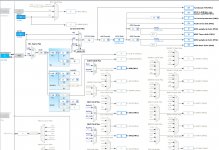
Last edited:
Technical documentation is provided.What ARM CPU chip pin will you connect to the GPIO header?
GPIO pins are clearly identified.
schematics for I2S DAC are freely provided and drivers source code provided.
Issue maybe the CPU is young, and documentation is not 100% complete.
Kernel 4 is under development. v4.6 & 4.7 look promising. it should be easiest to manipulate GPIO and external hadware.
What is the most important? Having all the user need in one box (like 4K TV box with S903 chips for $40) or having 1 DSP + 1 player + 1 amplifier + 1 PC to program the DSP, the knowledge requested to do that, etc...One may regret that the T.I. ARM CPU is not as powerful as the ARMLOGIC S905 (ODROID C2), or Actions Tech TM7059/S500 (Sparky), or Broadcom (Raspberry). Who really cares, dealing about audio DSP ? Are you willing to execute many 4,096-tap FIR filters? Are you sure you require such narrow frequency resolution? Do you intend doing room deconvolution? Do you know how sensible it is, to the mike (and ears) placement? Is it practical?
To be honest, I don't care if it is Linux, or bare metal... I care to develop a user centric system.
I understand you:I was a old game developper 20 years ago. I made games in assembly language, C and C++. But currently I love spend time on user value and less on technical line codes.On one side, you have people like me wanting to program them bare metal in C language, and possibly in assembler in the audio DSP routines.
I will start a new thread for this chip very soon.One could open a new diyAudio thread, dealing with this.
Good luck for your projects, and enjoy !
Q1 : What chip are you talking about ?To be honest, I don't care if it is Linux, or bare metal. I care to develop a user centric system. I was a old game developer 20 years ago. I made games in assembly language, C and C++. But currently I love spend time on user value and less on technical line codes. I will start a new thread for this chip very soon. Good luck for your projects, and enjoy !
Q2 : What value will perceive the user, in case you provide him beautiful menus and equalization curves, but don't provide him a way to measure his system in amplitude and in phase, before equalization and after equalization ?
Q3 : Have you noticed, the more IIR Biquads you engage, the more issues you get with the phases, which means that high-order IIR Biquad based crossovers are difficult to configure when the speakers depart from ideal. Okay, you may hope relying on ideal wideband speakers exhibiting no high frequency cone breakup resonances, apply on them some textbook crossover like Linkwitz-Riley, but why a crossover, then ?
Q4 : Can IIR Biquad filters adjust themselves, for the equalized speaker conforming to some user-specified target response curve, in amplitude and in phase ?
Q5 : Have you noticed, how fast users and customers vanish as soon as they are advised to rely on a mike ?
Try addressing those five questions.
Cheers,
Steph
The WOLFSON AUDIO CARD for Raspberry Pi.
Eventually to be used as bit-perfect SPDIF-in (no ASRC involved).
See here : wolfson-audio-card/carte-raspberry-pi-soundcard/dp/2347264
Selling price : less than $25.
This is the audio hub originally developed by Wolfson and Element14, for the old Raspberry Pi featuring the 26-pin expansion connector along with the "P5" 8-pin digital audio header.
The Wolfson Audio Card embeds :
- one WM5102 Audio Codec featuring stereo audio in (analog) and stereo audio out (analog),
- one WM8804 SPDIF transceiver featuring SPDIF-in and SPDIF-out,
- two WM7720 Digital Siicon Microphones.
The difficulty with such arrangement, is to properly configure the WM5102 using I2C. Get warned : the WM5102 datasheet is 334 pages long.
Fortunately there is a Raspberry distribution supporting the Wolfson Audio Card.
This webpage provides a Raspberry Pi Image from Element14 that contains support for the Cirrus Logic audio card : https://www.adafruit.com/products/1761
Beware of the 2 Gigabytes to be downloaded. This is massive Linux stuff.
One may try locating the WM5102 initialization source code, and copy-paste it to a STM32F4 or STM32F7 application.
For the ones only interested by the WM8804 SPDIF-in (listen from a CD player or from a PC), there exist a different way. The WM8804 is easy to configure using I2C. The WM8804 datasheet is only 66 pages long. Unfortunately, on the Wolfson Audio Card, the WM8804 I2S is passing trough the WM5102, prior reaching the "P5" 8-pin digital header that you'll hook on the STM32F4 Nucleo or STM32F7 Nucleo. Consequently, you may be tempted by soldering three wires on the WM8804 (I2S_LRCK, I2S_BCLK, I2S_TX) for directly providing audio to the Nucleo board, not to forget the MCLK that's also generated by the WW8804 to be considered as high quality "Audio Clock In" that you are obliged to provide as 256 x Fs clock for the Nucleo I2S blocks, operating as I2S slaves. Indeed, by choosing SPDIF as audio source, the WM8804 becomes the audio clock master, and the I2S master also. In case you rely on the STM32F7 SAI, you need to clock them from the "Audio Clock In" also, and configure them as "Asynchronous Slaves in I2S Protocol".
See the attached .jpg.
I'm also attaching the schematic on .pdf, as it tends to vanish from the web.
It vanishes from the web as there is a new version available, marketed as the "CIRRUS LOGIC AUDIO CARD" for Raspberry Pi. Such new version got developed after the purchase of Wolfson by Cirrus Logic. Such new version was required for hooking on the (larger) 40-pin expansion connector featured by the newest Raspberry Pi boards.
Such "CIRRUS LOGIC AUDIO CARD" for Raspberry Pi is available here : cirrus-logic-audio-card-for-rpi/dp/2448312
Selling price : less than $50.
I have not found the detailed schematic yet.
Cheers,
Steph
Attachments
-
Wolfson Audio Card - schematic diagram (version with 26-pin Raspberry and 8-pin P5).pdf325 KB · Views: 90
-
 Wolfson Audio Card for Raspberry - Raspberry connexions.jpg118.9 KB · Views: 232
 -
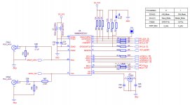 Wolfson Audio Card for Raspberry - WM8804 SPDIF transceiver.jpg145.7 KB · Views: 472
 -
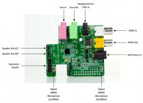 Wolfson Audio Card for Raspberry - Interconnects.jpg84.3 KB · Views: 248
Last edited:
Configuring the WM5102 using I2C.
Relying on the Raspberry Pi WM5102 support for configuring the WM5102 is impractical.
Better start from a clean sheet.
I went on Cirrus Logic website and found the required resources.
See the attached .jpg.
WM5102 : Smart Codec with Voice Processor DSP
Go in the "resources" tab.
Over there you will find "WISCE Setup" (.zip download) and "WM5102 Setup" (.zip download).
Once both are installed on your Windows computer, you ask WISCE to open a WM5102 project.
We need the WM5102 to act as transparent bridge between the WM8804 and the Raspberry PI "P5" connector. The Wolfson Audio Card schematic tells us that the WM5102 is receiving the WM8804 audio data on AIF2RX, and that the WM5102 is sending audio data on AIF1TX, to the Raspberry "P5".
In other words, we want the WM5102 to read the AIF2RX audio data, and to send it to the AIF1TX.
Using WISCE, we do three things :
1. Enable AIF2RX
2. Enable AIF1TX
3. Configure the AIF1 digital mixer, for having the AIF2RX acting as audio source for AIF1TX
While doing so, we see WISCE updating the historic, that one can save on a text file. Provided that you act in a clean way, this is what you are going to find in the historic file :
* ----- ------ -------------------- ------- --------- ------------------------------
* REG DATA ACCESS READ OR DEVICE
* INDEX VALUE TYPE WRITE ADDRESS COMMENT (for information only)
* ----- ------ -------------------- ------- --------- ------------------------------
0x55A 0x0001 SMbus_32inx_16dat Write 0x34 * AIF2 Rx Enables(55AH): 0001 AIF2RX2_ENA=0, AIF2RX1_ENA=1
0x519 0x0001 SMbus_32inx_16dat Write 0x34 * AIF1 Tx Enables(519H): 0001 AIF1TX8_ENA=0, AIF1TX7_ENA=0, AIF1TX6_ENA=0, AIF1TX5_ENA=0, AIF1TX4_ENA=0, AIF1TX3_ENA=0, AIF1TX2_ENA=0, AIF1TX1_ENA=1
0x700 0x0028 SMbus_32inx_16dat Write 0x34 * AIF1TX1MIX Input 1 Source(700H): 0028 AIF1TX1MIX_STS1=0, AIF1TX1MIX_SRC1=AIF2RX1
Such is the list of the registers you need to write, and the data you need to write in.
In summary, you need to write :
register 55A (hex) with data 0001 (hex)
register 519 (hex) with data 0001 (hex)
register 700 (hex) with data 0028 (hex)
That's all, what's regarding the required WM5102 audio data routing. Three lines of code.
In case the "by default" settings of the WM5102 don't match the "by default" settings of the WM8804, you may need to write more WM5102 registers what's regarding the AIF2 configuration.
In case the "by default" settings of the WM5102 don't match the "by default" settings of the I2S (or SAI) of the STM32F4 (or F7), you may need to write more WM5102 registers for defining the protocols (I2S/DSP 16bit/24bit master/slave), and the clocks.
Cheers,
Steph
Attachments
Configuring the WM8804 using I2C.
I went on Cirrus Logic website and found the required resources.
See the attached .jpg.
WM8804 : S/PDIF Digital Interface Transceiver
Go in the "resources" tab.
Over there you will find "WISCE Setup" (.zip download) and "Device Pack for WM8804" (.zip download).
Once both are installed on your Windows computer, you ask WISCE to open a WM8804 project.
The WM8804 being an uncomplicated chip, the only thing you can do using WISCE is to view all WM8804 registers, and to edit them by clicking on meaningful bit groups. Simple and efficient, provided that you read the datasheet.
While doing so, we see WISCE updating the historic, that one can save on a text file.
Cheers,
Steph
Attachments
Q1 : What chip are you talking about ?
Q2 : What value will perceive the user, in case you provide him beautiful menus and equalization curves, but don't provide him a way to measure his system in amplitude and in phase, before equalization and after equalization ?
Q3 : Have you noticed, the more IIR Biquads you engage, the more issues you get with the phases, which means that high-order IIR Biquad based crossovers are difficult to configure when the speakers depart from ideal. Okay, you may hope relying on ideal wideband speakers exhibiting no high frequency cone breakup resonances, apply on them some textbook crossover like Linkwitz-Riley, but why a crossover, then ?
Q4 : Can IIR Biquad filters adjust themselves, for the equalized speaker conforming to some user-specified target response curve, in amplitude and in phase ?
Q5 : Have you noticed, how fast users and customers vanish as soon as they are advised to rely on a mike ?
Try addressing those five questions.
Cheers,
Steph
Hi Steph,
thx for your feedback.
I will try to start a ODROID C2 thread as soon I will have answers on I2S.
Then we can discuss about your questions. My topic was on hardware choice and not how to implement functions inside. Issues remains the same on STM32 or other CPU...
I have ideas about your questions.
All the best for all talents here on STM32
regards,
Christian
Thank you ;-) I will need your encouragements for the Stm32 stuff. Seems not so easy event to squeeze little things out of that little thing. I struggle to mix two example for play some table to The I2S => DAC, using the highest software layer :-(
However, I feel that those STM32 have an edge over SBC on 3 items:
- the development board expose all the pins, which is not the case in more complex SBC, and is often an issue for the audio purposes,
- All the audio features are readily available without having to wait for extra kernel developments
- no harware mods to perform.
I'll follow your thread. Please post the link here.
Best regards,
JMF
- Status
- This old topic is closed. If you want to reopen this topic, contact a moderator using the "Report Post" button.
- Home
- Source & Line
- Digital Line Level
- Can low jitter be achieved with STM32 microcontroller