Søren - thanks for the above. Was a bad capacitor in the end. Seemed to be a defective opamp based on the image below but after replacing the OPA365 the issue was still there so a check of the caps found one that was resistive, not dead-shorted, fortunately. Back up and running now.
After the repair a quick check on an AP could not get near your stated figure for THD at -60db in the Quick Specifications. Was that figure measured with the board in balanced mode?
Based on the FFT in single ended mode. Note that it is THD, not THD+N, it's pretty hard to measure at that low level, noise have this habit of getting in the way.... Do the FFT's instead and compare with the plots on page one on this thread. If you have too high even harmonics, check the vref voltages.
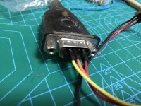
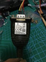
I used this USB to serial cable (Aten UC-232A) which works with dam1021. As I only connect TX, RX and Gnd, I guess it doesn't damage the card yet.
So do I need to add a TTL to RS232 adapter in between?
Why not just buy the right cable, they're around $10....
Why not just buy the right cable, they're around $10....
Thanks. I have done updating. I have several USB serial and USB TTL cards, just I didnt take the TTL to use until another member told me.
Why dont you update the manual to add a word "TTL" to give a hint to people instead? I do a full text search of the dam1121 manual but I can only find the word "serial" but not "ttl".
TTL and RS232 both belongs to serial. TTL and RS232 must be specified. Otherwise people would just need to trial and error.
http://www.soekris.dk/download/dam1121/dam1121_manual.pdf
That’s a link to the dam1121 manual.
On page two starts a table for connection of J2. It is clearly written there that TX and RX is 3,3V Level.
On page four, in the operating condition is written, that input and output pins (except clock) is input max 3,9 level logic high, and output 3,3V.
The dam1121 is for advanced DIYer I would say. It requires more careful considerations.
If you have more questions don’t hesitate to ask!
fair enough. I just give my advice for Soren to consider. I know he has a strong mind for what he is doing so I dont expect there'd be any change made at last.
In the end, I have done updating and finished the DAC building, will share some photos later.
fair enough. I just give my advice for Soren to consider. I know he has a strong mind for what he is doing so I dont expect there'd be any change made at last.
In the end, I have done updating and finished the DAC building, will share some photos later.
Actually TTL would be even more wrong.... It is 3.3V levels, just as stated in manual, which you're supposed to read....
How can one multichannel the dam1121?
for example 4 channels (synchronous)?
Must the slave get it's i2s from master board then? Is it at all possible to feed SPDIF into a slave board?
Søren did you have time to look at the code yet?
Based on the FFT in single ended mode. Note that it is THD, not THD+N, it's pretty hard to measure at that low level, noise have this habit of getting in the way.... Do the FFT's instead and compare with the plots on page one on this thread. If you have too high even harmonics, check the vref voltages.
Will get round to it. Thanks.

This is the Text from soekris.dk about the dam1121
Sören, do you already have a solution on how to configure Multichannel?
Soekris OEM line
The Soekris Engineering discrete R-2R sign magnitude DAC technology is now available as a small OEM module designed to be integrated in all kinds of audio products.
Input is I2S and SPDIF, with reclocking FIFO. Clocking is with low jitter digital programmable oscillator, either on board or off board. Multiple board can be syncronized for balanced or multichannel use.
Sören, do you already have a solution on how to configure Multichannel?
This is the Text from soekris.dk about the dam1121
Sören, do you already have a solution on how to configure Multichannel?
It have always be possible to connect multiple slaves to one master, with the digital inputs going to the master. That is mainly for doing digital crossovers using the biquads in the multiple dam1121's, or for balanced or parallel operation.
As I understood your initial question: how to connect boards using separate inputs to each board, like having an external dsp doing the digital crossovers, right ? That is currently not possible, they must all run as masters if you want to use their i2s or spdif inputs.
As I understood your initial question: how to connect boards using separate inputs to each board, like having an external dsp doing the digital crossovers, right ? That is currently not possible, they must all run as masters if you want to use their i2s or spdif inputs.
The Idea I have in mind is synchronous Multichannel. Synchronous Multichannel is written at the main page of the description of the dam1121 as an purpose.
Which means, the boards each will need discrete inputs yes.
As I will have one external SI570 (connected to one dam1121) and a 1:4 LVDS Buffer, can I not feed the clock to all dam1121 boards even if they are configured as masters? Will this be synchronous?
For a board to use its own input, it must be master. But a master will not disable its oscillator, which are required to use an external clock.
It don't sound that complicated to implement a master mode with oscillator disabled, the problem with all changes are testing and verifying....
Of course you could just remove all onboard oscillators.... Then connect the external oscillator to one of the master, it will then recognize and use it....
Finally I have success using a USB-RS232 adapter to update the firmware to 1.21! Yay.
I want to upload TNT's filters pack - do I use the same method? I can't seem to find how to do that or switch the filters. Sorry, its really late here.
Ok, loaded the TNT filters pack. Yay
It don't sound that complicated to implement a master mode with oscillator disabled, the problem with all changes are testing and verifying....
All right. Is this something you have on your agenda, to make the dam1121 meet it's product description?
Of course you could just remove all onboard oscillators.... Then connect the external oscillator to one of the master, it will then recognize and use it....
One more thing, can the boards be in sync to each other when they are all masters?
Hi,
I'm currently using a minidsp Minisharc with three I2S outputs feeds three stereo DAM1121. The three DAM are all masters, each board synchronize his clock by the onboard oscillator. This works fine.
As an improvement I thought about using of one central clock to feed the three DAM configured as slaves. If I understand the schematic auf Soren's website I would say, that this shall work. With the master-slave configuration is the slave board feeded by the master board via I2S.
Best Regards, Adam
...
As an improvement I thought about using of one central clock to feed the three DAM configured as slaves. If I understand the schematic auf Soren's website I would say, that this shall work. With the master-slave configuration is the slave board feeded by the master board via I2S.
Søren, is my understanding right? Three boards supplied by a central clock LVDS synchron with the external (minidsp) I2S. Thank you for a short statement.
Best Regards, Adam
- Home
- Source & Line
- Digital Line Level
- Building with the Soekris dam1121