Got some work done today, though some parts I thought would arrive didn't.
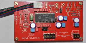
PCM1794 one of the boards, now only missing 2pcs 1206 300R resistors and the 3pin screw terminal.
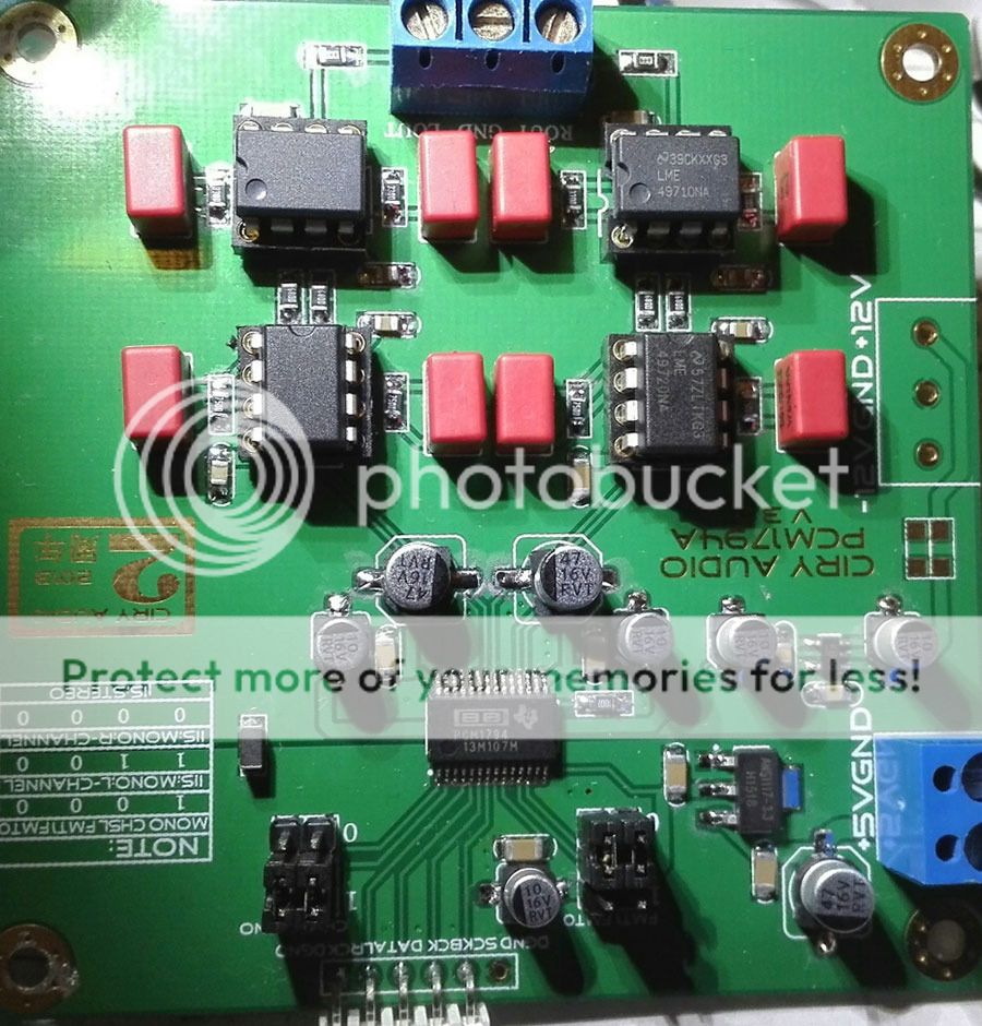
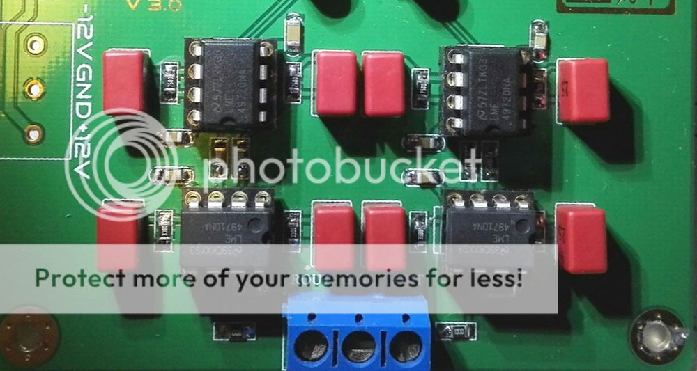
Opamps in place, I hope these will work as direkt drop-in replacements for the NE5532/5534 that was supposed to populate these spots.
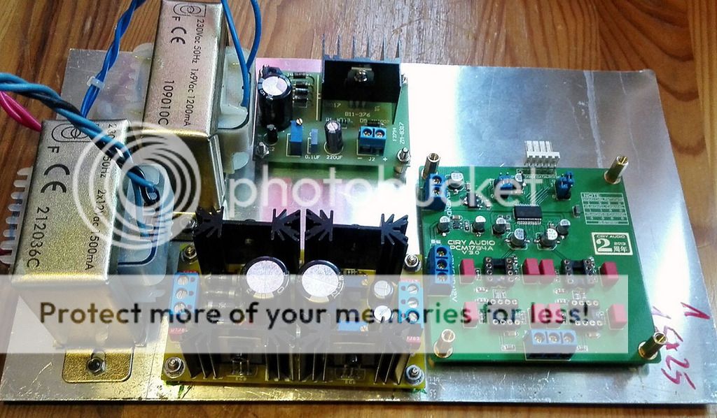
I also did some mock-up layout, using a 36VA 12-0-12Vac EI and a 0-9Vac 1.2A EI.
A shunt reg for the +/-12Vdc (I hope the 200mA per rail will suffice for the opamps) and an LM317 for the +5Vdc.
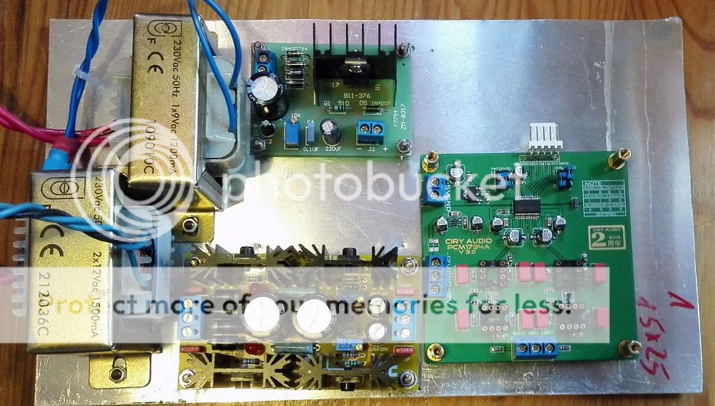
I also need to fit a reciever board there, so either I make a small WM8805 board or I buy a tekdevice WM8804 board(those are very small)
I think I completed the AD1896A board, I need to go over it with the DMM some more to make sure. I hope I didn't overheat the AD1896A when removing it from one adapter board and soldered it to another.
Somehow the original adapter board had gotten damaged. I've had the IC for a few years as it was intended for another project.
PCM1794 one of the boards, now only missing 2pcs 1206 300R resistors and the 3pin screw terminal.

Opamps in place, I hope these will work as direkt drop-in replacements for the NE5532/5534 that was supposed to populate these spots.

I also did some mock-up layout, using a 36VA 12-0-12Vac EI and a 0-9Vac 1.2A EI.
A shunt reg for the +/-12Vdc (I hope the 200mA per rail will suffice for the opamps) and an LM317 for the +5Vdc.


I also need to fit a reciever board there, so either I make a small WM8805 board or I buy a tekdevice WM8804 board(those are very small)
I think I completed the AD1896A board, I need to go over it with the DMM some more to make sure. I hope I didn't overheat the AD1896A when removing it from one adapter board and soldered it to another.
Somehow the original adapter board had gotten damaged. I've had the IC for a few years as it was intended for another project.


Actually took pics with the DSLR today, but in bad lighting. Don't have a good flash for it yet.
Some pics where take with my phone before taking out the DSLR.
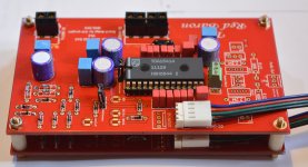
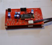
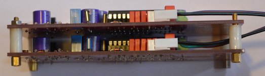
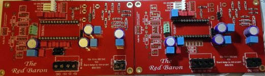
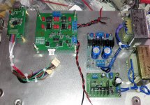
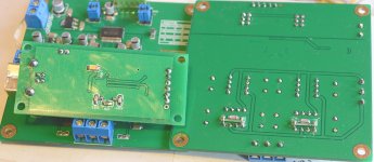
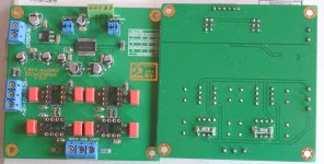
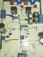
Two Red Baron boards populated, as much as they'll be populated for now atleast. One partially populated as I discovered I didn't have enough of the MKS02 220nF Wima's.
As you can see in the pics, space is a concern in the chassis, so I've used the lowest profile connectors I had and left very little space between the two board intended to be in parallel.
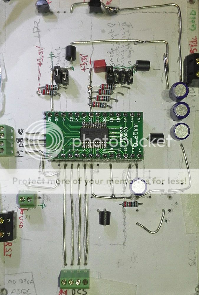
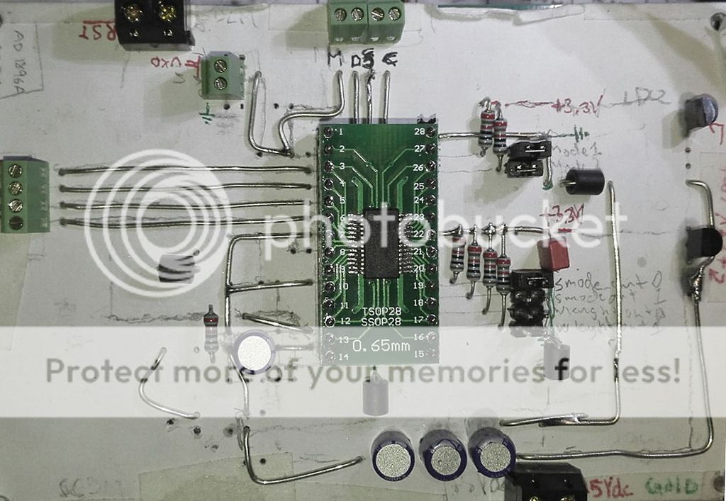
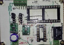
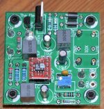
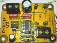
I also made some progress on a second WM8805 board (perf board), smaller with mainly SMD components using two MIC5205-3.3V LDO's on the board so it can be powered by a single +5Vdc supply.
I use the paper on the perf board to make layout easier, I don't necessarily follow what I've drawn exactly but it's a decent way to get an overview.
Some pics where take with my phone before taking out the DSLR.
Two Red Baron boards populated, as much as they'll be populated for now atleast. One partially populated as I discovered I didn't have enough of the MKS02 220nF Wima's.
As you can see in the pics, space is a concern in the chassis, so I've used the lowest profile connectors I had and left very little space between the two board intended to be in parallel.
I also made some progress on a second WM8805 board (perf board), smaller with mainly SMD components using two MIC5205-3.3V LDO's on the board so it can be powered by a single +5Vdc supply.
I use the paper on the perf board to make layout easier, I don't necessarily follow what I've drawn exactly but it's a decent way to get an overview.
Attachments
-
 Red_Baron_boards_1_and_2_populating_4.jpg307.8 KB · Views: 88
 -
 Red_Baron_boards_1_and_2_populating_7.jpg215.4 KB · Views: 69
 -
 Red_Baron_boards_1_and_2_populating_6.jpg313.3 KB · Views: 66
 -
 Red_Baron_boards_1_and_2_populating_2.jpg119.3 KB · Views: 65
 -
 Red_Baron_boards_2_and_3_populating_1.jpg208.1 KB · Views: 50
 -
 WM8805_mkIII_populating_3.jpg252.9 KB · Views: 51
 -
 WM8805_mkIII_populating_4.jpg119.4 KB · Views: 68
I've one Flea PCB more or less completed except for the voltage reg.
I don't recall where I read it, but IIRC you can use a lower supple voltage by substituting the 7812 for a lower voltage reg. I don't recall what the lowest working 78xx was though...
I've been looking at several options for active I/V for both the parallel TDA1541A, single TDA1541A and dual PCM1794.
I found a schematic of a bjt based discrete I/V "Rbroer" IIRC.
Now, I don't understand how to modify this circuit for parallel TDA1541A's or for PCM1794. I also don't understand how and what to set using the trimpots.
My understanding of I/V is what it does basicaly, current to voltage...that's where my knowledge on this, to me, new area ends.
I found a schematic for OPA1632(I have two of those) as I/V as well.
Being a balanced opamp, one of these could handle I/V for L pos and L neg for example for one PCM1794 if I understood it correctly.
Following that I'd need the balanced to SE op amp and filter I guess.
New areas in this hobby gives new headaches, but at the same time, it's fun to learn new things")
I don't recall where I read it, but IIRC you can use a lower supple voltage by substituting the 7812 for a lower voltage reg. I don't recall what the lowest working 78xx was though...
I've been looking at several options for active I/V for both the parallel TDA1541A, single TDA1541A and dual PCM1794.
I found a schematic of a bjt based discrete I/V "Rbroer" IIRC.
Now, I don't understand how to modify this circuit for parallel TDA1541A's or for PCM1794. I also don't understand how and what to set using the trimpots.
My understanding of I/V is what it does basicaly, current to voltage...that's where my knowledge on this, to me, new area ends.
I found a schematic for OPA1632(I have two of those) as I/V as well.
Being a balanced opamp, one of these could handle I/V for L pos and L neg for example for one PCM1794 if I understood it correctly.
Following that I'd need the balanced to SE op amp and filter I guess.
New areas in this hobby gives new headaches, but at the same time, it's fun to learn new things
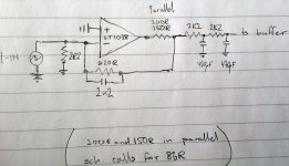
I found this schematic, it's intended for PCM1972 and should work nicely for PCM1794 and maybe two parallel TDA1541A as well?
https://www.by-rutgers.nl/PDFiles/Mature%20IV-converter.pdf
I thought I might try it, but with a discrete stage after the 2K2 - 470pF - 2K2 - 470pF filter. Would that work and make any sense?
I was thinking about adding a ferrite bead before the first 2K2 resistor, or would that change the filter characteristics(spelling?) alot?
I've also recieved some AD844's the other day.
I've read alot of people seem to like them stacked and feeding a separate buffer from the TZ pin.
So many options so little time lol
I know I build a ton of stuff, the plan is to compare the different combinations and then keep two dac's with the two, to my ears, best combinations.
Attachments
Long time no update.
But things have progressed, slowly but surely
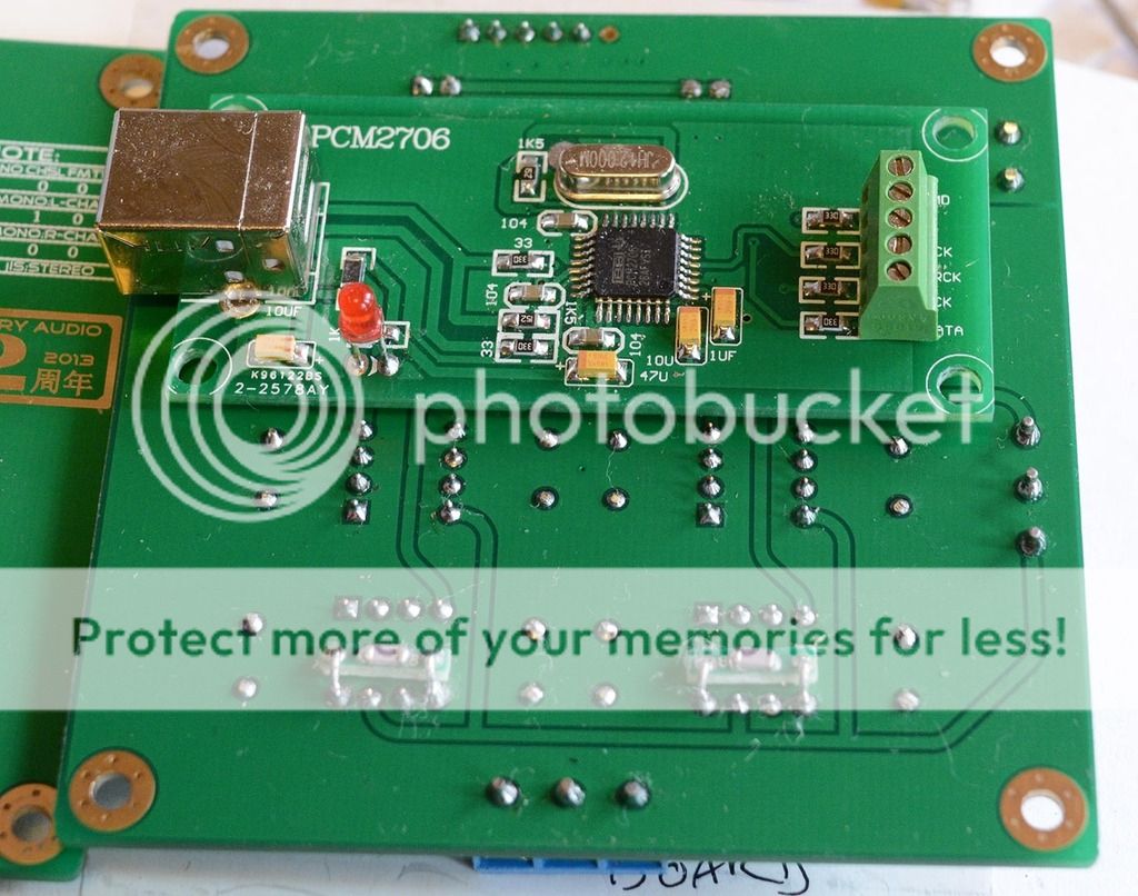
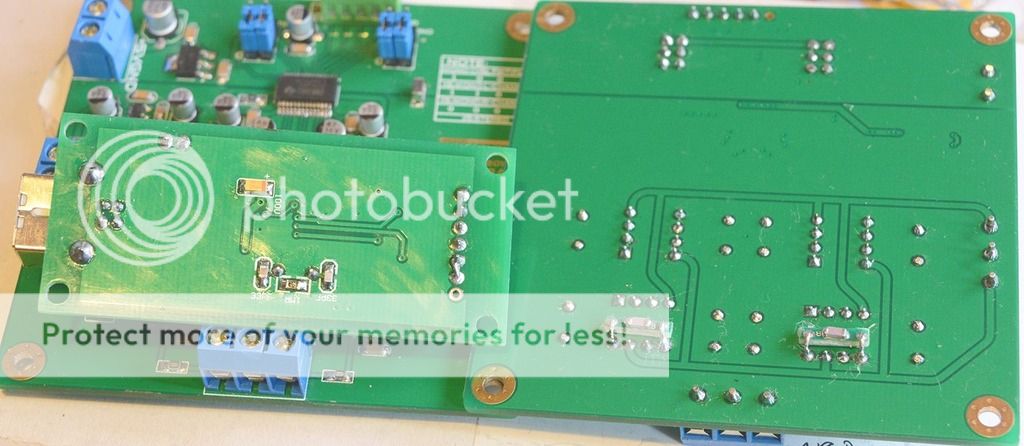
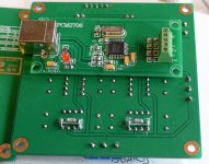
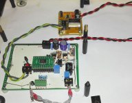
I got a PCM2706 board in the mail about a week ago, so I figured why not try that with the two PCM1794 boards I have populated?
Only one of the boards are in place in the pic as the other will be right on top of it making getting to terminals etc hard once mounted.
Question:
In differential mode using two boards (I2S differntial mono Right for one and Left for the other), I get a balanced signal out?
How do I best convert that to SE if that is the case?
I have two pairs of Edcor XSM transformers, 600:600 and 10K:10K.
I'm also open to building something on perf board, a discrete balanced to SE preferably if that is possible. There's plenty of space (for once lol) but I'd rather not need another PS transformer in this enclosure.
The ones fitted are:
0-9VAC 1200mA
12-0-12VAC 1500mA
That should be plenty?
Edit:
Forgot to add.
I've also started a AD844 (tripple stacks) I/V + jfet buffer board for the single TDA1541A Red Baron board.
One stack of AD844 is one IC short atm as I'm waiting for it to arrive.
But things have progressed, slowly but surely
I got a PCM2706 board in the mail about a week ago, so I figured why not try that with the two PCM1794 boards I have populated?
Only one of the boards are in place in the pic as the other will be right on top of it making getting to terminals etc hard once mounted.
Question:
In differential mode using two boards (I2S differntial mono Right for one and Left for the other), I get a balanced signal out?
How do I best convert that to SE if that is the case?
I have two pairs of Edcor XSM transformers, 600:600 and 10K:10K.
I'm also open to building something on perf board, a discrete balanced to SE preferably if that is possible. There's plenty of space (for once lol) but I'd rather not need another PS transformer in this enclosure.
The ones fitted are:
0-9VAC 1200mA
12-0-12VAC 1500mA
That should be plenty?
Edit:
Forgot to add.
I've also started a AD844 (tripple stacks) I/V + jfet buffer board for the single TDA1541A Red Baron board.
One stack of AD844 is one IC short atm as I'm waiting for it to arrive.
Attachments
Last edited:
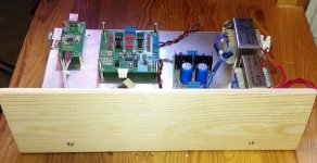
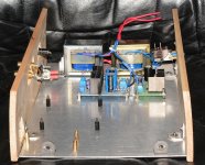
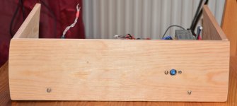
Made some progress with the enclosure for the dual PCM1794 NOS DAC.
I'm really very very bad at working with wood, I can cut a straight line if my life depended on it lol.
For instance, I discovered that the panel I bought wasn't flat when I got home. Not that it matters, it will make fitting the sides harder though.
I'm really very very bad at working with wood, I can cut a straight line if my life depended on it lol.
For instance, I discovered that the panel I bought wasn't flat when I got home. Not that it matters, it will make fitting the sides harder though.
Attachments
Small update again. I keep forgetting to update this...
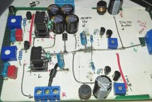
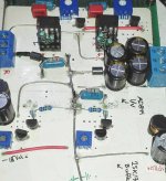
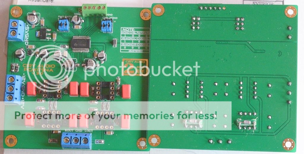
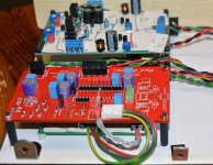
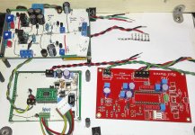
PCM1794 boards are slightly reworked and I hope I didn't kill anything as a 0805 resistor I desoldered apparently wound up under one of the DIP8 sockets, maybe that is what has caused the noise from this DAC?
Anyway, here's the PCM2706 board and the PCM1794 boards.
I've added 22pF between pin5 and pin8 on the single opamps (LT1028 for now, I'll also try LME49710NA).
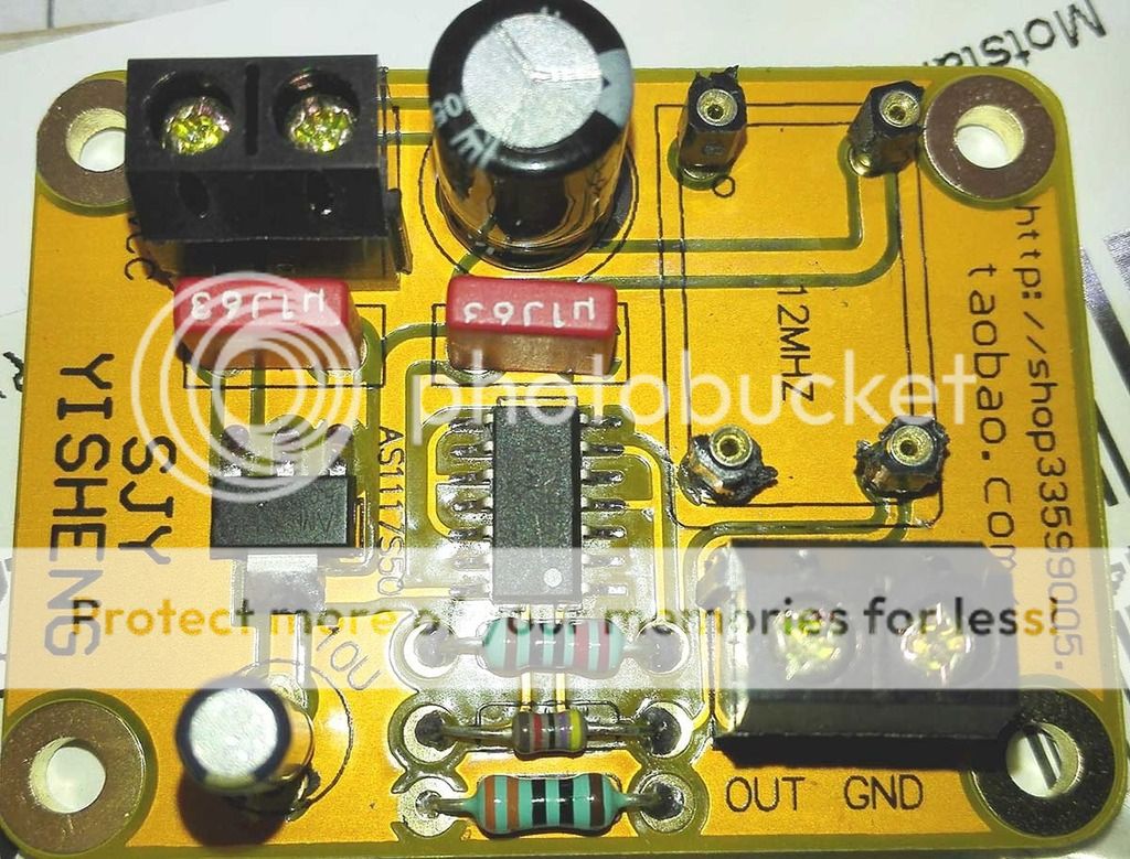
I've also built two Flea boards. One for the AD1896A TCXO.
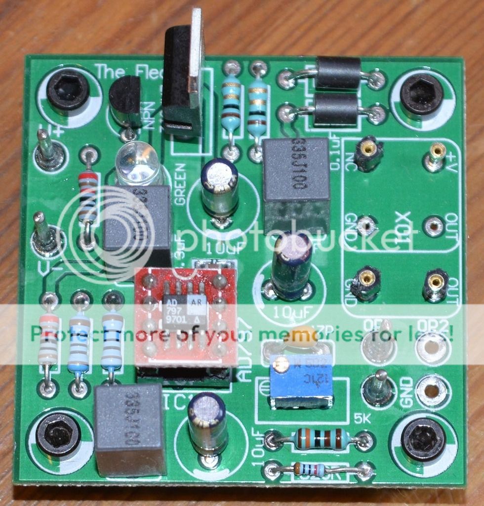
I've yet to test the Flea boards though, and I haven't even read up on what the trimpot does, though I guess it's for voltage adjustment.
One board for 12Mhz TCXO that is not a Flea.
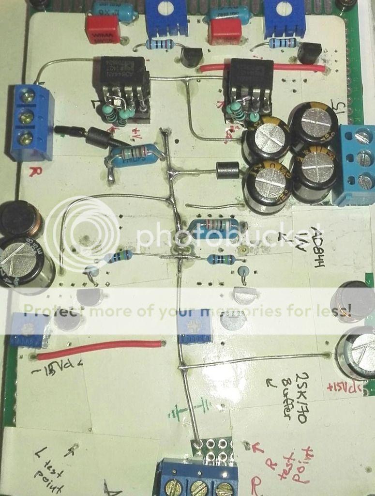
I've completed, but not tested, the tripple stack AD844 I/V + jfet buffer board. A perf board build that is not very pleasing for the eyes.
Well that's it for this update.
PCM1794 boards are slightly reworked and I hope I didn't kill anything as a 0805 resistor I desoldered apparently wound up under one of the DIP8 sockets, maybe that is what has caused the noise from this DAC?
Anyway, here's the PCM2706 board and the PCM1794 boards.
I've added 22pF between pin5 and pin8 on the single opamps (LT1028 for now, I'll also try LME49710NA).


I've also built two Flea boards. One for the AD1896A TCXO.

I've yet to test the Flea boards though, and I haven't even read up on what the trimpot does, though I guess it's for voltage adjustment.
One board for 12Mhz TCXO that is not a Flea.

I've completed, but not tested, the tripple stack AD844 I/V + jfet buffer board. A perf board build that is not very pleasing for the eyes.

Well that's it for this update.
Attachments
-
 PCM2706_dual_PCM1794_re_populating_8.jpg246.4 KB · Views: 48
 -
 PCM2706_dual_PCM1794_re_populating_7.jpg167.5 KB · Views: 41
 -
 PCM2706_dual_PCM1794_re_populating_9.jpg166 KB · Views: 46
 -
 PCM2706_dual_PCM1794_re_populating_10.jpg225.2 KB · Views: 33
 -
 Flea_PCB_populated_2.jpg206.5 KB · Views: 36
 -
 Buffered_tcxo_populated_5.jpg174.2 KB · Views: 29
 -
 AD844_IV_and-Jfet_buffer_board_populating_13.jpg124.4 KB · Views: 31
Small update time.
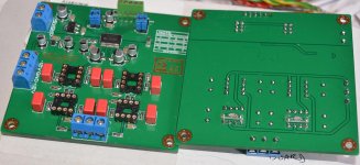
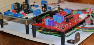
I've started trying layouts for the single Red Baron DAC.
I'm considering running it NOS, but with upsampling via AD1896A.
I've put together my "own" WM8804 board and a WM8805 board.
Board in the background is the AD844 triple stack I/V followed by a jfet buffer.
I haven't figured out how to best fit the voltage regulators. I need:
+3.3Vdc
+5Vdc x3 (not neccesarily 3 regs, but 3 consumers)..4 if I decide to use the AD1896A board.
-5Vdc
+15Vdc
-15Vdc x2 (here I should probably use two regs as one is for the I/V & buffer and the other for the TDA1541A.
I've used very good parts, I think (without going overboard), on the Red Baron board and the I/V + buffer board
Anyway, progress and some pics.
Attachments
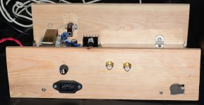
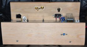
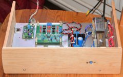
Done some work on the enclosore for the dual PCM1794 DAC.
I've temporarily put a WM8804 board from TekDevice in there to see if I can get sound from the dual PCM1794's.
I've sanded down one side of the front and back pieces to follow the curve of the side pieces.
I'll use filler to shape it before painting/using veneer(or what the "see through" paint is called).
I've not decided what to use as "lid" yet. Maybe smoked plexi glass or something? I'll see what I end up using.
Attachments
Long time, no update
Time for a small update.
Writing from my phone as I'm on my way to get my knees checked with an mri.
I've had boards made for the SM5814.
It was the first layout I ever sent of to a board house.
It had two sloppy errors that was easily corrected though.
I then sent a layout of a 4 rail tracking pre regulator board and those came back working just fine.
I needed more rails on small-ish footprint than the available LT1083 and lm3x7 boards offered.
The jfet/tube hybrid output I used in the analog metric DAC (and that atleast one other I know off have used and like) will be used in the dual Red Baron DAC as well.
I have ordered boards for that a few days ago as I prefer PCB's over point-to-point now that I'm getting proficient at using Eagle.
I'm working on a dual WM8740 board with wm8804 as reciever IC. It'll have dual differential output.
My thinking is using transformers for balanced to SE and for filtering.
First priority is getting the dual Red Baron DAC done though.
- Status
- This old topic is closed. If you want to reopen this topic, contact a moderator using the "Report Post" button.
- Home
- Source & Line
- Digital Line Level
- Modular DAC project, questions and updates