One little tip: Ceramic chip cap manufacturers usually advise against hand soldering because it can easily create temperature gradients across the part that end up creating cracks, eventually causing the cap to fail short later in life. (Leaded ceramics almost never fail, surface-mount ones do so quite regularly. Good job! ") ) Therefore avoid directly touching the cap with the iron tip if at all possible, just heat up the solder.
) Therefore avoid directly touching the cap with the iron tip if at all possible, just heat up the solder.
) Therefore avoid directly touching the cap with the iron tip if at all possible, just heat up the solder.Dammit! I just spotted a mistake on my previous post #16:
I say ..."replaced 2n2 caps labeled C68, C68, C12 and C15 with Panasonic film caps"...
obviously, one of the two C68 must be something else!
We will have to rely on the modders (Calderes?) to identify who the second 2.2nF cap is: My DEQ is in a rack at my workplace, I'm not going to open it up to find that.
My guess is it will be C67, or something near...
Sorry.
I noticed, but thanks for making sure that I noticed. I'll figure it out and let everyone know.
As for my progress...Yesterday I spent forever trying to decided on which caps to buy...
So I have a question, but forgive me because I am combining this mod with stef1777's awdiy.com capacitor replacement mod which is much more broad, and since this thread has been raised from the dead maybe I can get a quick response from someone here so I can get on with the full purchase of caps which includes the film caps that pertain to this thread's mod in particular.
So PierOlo, you used polyphenylene Sulfide (PPS) Film caps for the surface mounts, no questions there.
But for larger radial capacitors, stef1777 (from diyaudio but also his own awdiy) has suggested Nichicon UHD, Oscon SH (which I think are now Panasonic Oscons aka aluminum organic polymer), Elna Silmic II, as well as Panasonic FM series electrolytics! And there are many subtle differences!
First of all, I found it odd that Nichicon UHD was suggested since it is not Nichicons "high grade audio" series. There are a few in that category but Nichicon UKA is one of them.
The main difference between the UHD and UKA is that the UHD has larger ripple and leakage and different (worse?) frequency coefficients.
For example, a 47uF 25v UHD cap has 250ma ripple, 11ua leakage, and an impedance defined by frequency coefficient of 0.55 at 120hz , 0.85 at 1khz and 1.0 at 10khz+.
A 47uF 25v UKA "high grade audio" cap has 83ma ripple, 4ua leakage, but an impedance defined by frequency coefficient of 1.0 at 120hz, 1.57 at 1khz and 2.0 at 10khz. Is that better or worse than UHD?!
The Elna Silmic II and Panasonic FM series have similar ratings to the Nichicon UHD except the Elna Silmic is rated at 85*C and all others are 105*C. Also the frequency coefficients are slightly different.
Please correct me if I am confused about what an OSCON is because Sanyo OSCONS aren't being produced anymore and Panasonic and Nichicon both describe their OSCONS as aluminum organic polymer type.
So as I understand it, OSCONS have way higher ripple and leakage but they seem to have much lower frequency coefficients. By higher ripple and leakage I mean, 1500ma ripple (vs 80-250ma for UKA or UHD) and 250ua leakage (vs 4-11ua with UKA or UHD) with 20-60mohm ERS and frequency coefficients of 0.05 at 120hz, 0.3 1khz, 0.7 10khz+
OSCONS are way more expensive too...
So... should I go for lowest ripple like the "high grade audio" UKA series Nichicon? Something in the 200-300ma range of ripple like Nichicon UHD/Pansonic FM/Elna SilmicII? Or 1500ma ripple like Panasonic OSCON?
And should I avoid the Elna Silmic because it is only 85*C rated?
Can someone explain the importance of ripple, leakage, and perhaps help me understand the difference between ERS and frequency coefficients? (Just a better or worse for this specific task is fine, I don't need the complex explanation for now
Sorry I know this is a bit off topic, but this larger purchase includes the caps for the mod that pertains to this thread and my confusion is delaying the process! Any help would be greatly appreciated
I'll figure it out and let everyone know. As for my progress...Yesterday I spent forever trying to decided on which caps to buy...
So I have a question, but forgive me because I am combining this mod with stef1777's awdiy.com capacitor replacement mod which is much more broad, and since this thread has been raised from the dead maybe I can get a quick response from someone here so I can get on with the full purchase of caps which includes the film caps that pertain to this thread's mod in particular.
So PierOlo, you used polyphenylene Sulfide (PPS) Film caps for the surface mounts, no questions there.
But for larger radial capacitors, stef1777 (from diyaudio but also his own awdiy) has suggested Nichicon UHD, Oscon SH (which I think are now Panasonic Oscons aka aluminum organic polymer), Elna Silmic II, as well as Panasonic FM series electrolytics! And there are many subtle differences!
First of all, I found it odd that Nichicon UHD was suggested since it is not Nichicons "high grade audio" series. There are a few in that category but Nichicon UKA is one of them.
The main difference between the UHD and UKA is that the UHD has larger ripple and leakage and different (worse?) frequency coefficients.
For example, a 47uF 25v UHD cap has 250ma ripple, 11ua leakage, and an impedance defined by frequency coefficient of 0.55 at 120hz , 0.85 at 1khz and 1.0 at 10khz+.
A 47uF 25v UKA "high grade audio" cap has 83ma ripple, 4ua leakage, but an impedance defined by frequency coefficient of 1.0 at 120hz, 1.57 at 1khz and 2.0 at 10khz. Is that better or worse than UHD?!
The Elna Silmic II and Panasonic FM series have similar ratings to the Nichicon UHD except the Elna Silmic is rated at 85*C and all others are 105*C. Also the frequency coefficients are slightly different.
Please correct me if I am confused about what an OSCON is because Sanyo OSCONS aren't being produced anymore and Panasonic and Nichicon both describe their OSCONS as aluminum organic polymer type.
So as I understand it, OSCONS have way higher ripple and leakage but they seem to have much lower frequency coefficients. By higher ripple and leakage I mean, 1500ma ripple (vs 80-250ma for UKA or UHD) and 250ua leakage (vs 4-11ua with UKA or UHD) with 20-60mohm ERS and frequency coefficients of 0.05 at 120hz, 0.3 1khz, 0.7 10khz+
OSCONS are way more expensive too...
So... should I go for lowest ripple like the "high grade audio" UKA series Nichicon? Something in the 200-300ma range of ripple like Nichicon UHD/Pansonic FM/Elna SilmicII? Or 1500ma ripple like Panasonic OSCON?
And should I avoid the Elna Silmic because it is only 85*C rated?
Can someone explain the importance of ripple, leakage, and perhaps help me understand the difference between ERS and frequency coefficients? (Just a better or worse for this specific task is fine, I don't need the complex explanation for now
Sorry I know this is a bit off topic, but this larger purchase includes the caps for the mod that pertains to this thread and my confusion is delaying the process! Any help would be greatly appreciated
Okay, well...shame on me for such a lengthy, mostly off-topic post. I finally found a good (great) all-in-one information page that answered my questions.
How to Pick Audio Capacitors | Fenestration & Debauchery
I'll just duplicate the few summary statements the author made at the end of the article:
---------------------------
Signal capacitors: low impedance, long life.
Filter capacitors: low leakage, long life.
Quick and dirty test for people who don’t want to wade through the specs: Low tan(delta), low dissipation factor, or high Q factor is better.
--------------------
Also, higher ripple on the cap specs is better (ripple itself is bad, but the spec is actually "resistance to" ripple, rather than ripple itself), but this spec usually comes with a trade off in leakage and resistance and if the caps are rated above the possible DC voltage fluctuation, you won't benefit from going higher. If actual DC ripple exceeds the ripple spec of the cap, it heats up and shortens its life (potentially).
And 85*C should be fine, although most are rated to 105*C anway
So low impedance should should be my target and if I can get Film caps I should because they don't degrade like electrolytics.
Sound about right?
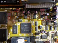
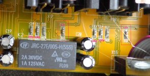
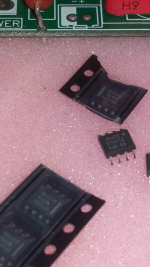
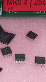
Okay, here are some high resolution photos that show the caps that PierOlo replaced.
On the bottom of the Analog(input/output) Board, there are four 390p caps - C70, C69, C67, and C66. There are also two 2n2 caps C68 and C65.
On the top of the Analog(input/output) Board, there are two more 2n2 caps C12 and C15.
In the photos, I have also tagged the 100p caps which could also be replaced if you are a sadist. ;-)
Don't confuse 100n with 100p, I highlighted some labels that we obscured but only for completeness, not because they need to be changed.
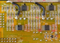
On the Digital board (with DACs) you will see that this is actually VERSION 2.5!!! So the caps listed on sites like awdiy.com are actually a little off! The changed the AK5393VS and now use a smaller CS5381-KZZ from Cirrus Logic. So they have three 1uF 50V radials now...anways...the caps that PierOlo swapped should still the same.
The picture of the digital board shows all the possible candidates to recap but for this thread, C18/C19 (1n5) and C30/C31/C32 (10uf 10V bypass caps added on top) are the caps of interest (but might as well add 10uf 10V bypass caps to C28 and C29 while you're at it!
On the bottom of the Analog(input/output) Board, there are four 390p caps - C70, C69, C67, and C66. There are also two 2n2 caps C68 and C65.
On the top of the Analog(input/output) Board, there are two more 2n2 caps C12 and C15.
In the photos, I have also tagged the 100p caps which could also be replaced if you are a sadist. ;-)
Don't confuse 100n with 100p, I highlighted some labels that we obscured but only for completeness, not because they need to be changed.
On the Digital board (with DACs) you will see that this is actually VERSION 2.5!!! So the caps listed on sites like awdiy.com are actually a little off! The changed the AK5393VS and now use a smaller CS5381-KZZ from Cirrus Logic. So they have three 1uF 50V radials now...anways...the caps that PierOlo swapped should still the same.
The picture of the digital board shows all the possible candidates to recap but for this thread, C18/C19 (1n5) and C30/C31/C32 (10uf 10V bypass caps added on top) are the caps of interest (but might as well add 10uf 10V bypass caps to C28 and C29 while you're at it!
Attachments
Don't bypass C29 and C28! That was true for the v2 board, but on the v2.5 board (different ADC chip) C11 and C12 are the ones you want to bypass.
C29 and C28 are .01uF as they should be, but could also be replaced with film caps.
I'll be continuing this journey on my new thread specific to the v2.5 board here:
http://www.diyaudio.com/forums/digital-line-level/305517-deq2496-v2-5-2017-recap-opamp-upgrade.html#post5025760
Post #12 on that thread explains why C11 and C12 are the ones to bypass.
after studying the new cirrus logic chip that replaced the akm adc, I think we'd better hold off on bypassing C11 and C12. (if they are proper C0G 10uF ceramics then they should be fine without modification) Please follow the thread I referenced in post #31 if you want more information.
The v2.5 board is just too different to be able to utilize instructions from previous mods.
The v2.5 board is just too different to be able to utilize instructions from previous mods.
Wow!
long monologue by Calderes since my last visit, so I'll chime in and give him a little company...
So the identity of the mystery cap on the analog board would be C65. One thing solved.
It would appear the two 220p caps I missed are still on the run, as I do not see them on the analog board photos. (which are, by the way, very useful. That's what I should have done back then- thanks Calderes!)
"So PierOlo, you used polyphenylene Sulfide (PPS) Film caps for the surface mounts, no questions there."
uh, I never sais that! I did put in film caps, but I do not remember which variety. I just aimed for film caps, and not for top-of-the-line esoteric über stuff. I really have no interest in that esoteric stuff... If I find my original invoice from DigiKey I'll be able to say exactly what I did put in, but don't hold your breath- that was long ago...
All the electrolytics on the output section are doing is DC blocking. Their ripple-suppressing capabilities are irrelevant in that situation. I see that you seem to be going overboard about caps to replacement on the digital board... I see no point in replacing every electrolytic caps for the fun of it unless they are directly involved in the audio path. My prsonnal goal in this mod was just to correct a fundamental desing flaw (bad capacitor type used in audio path that do cause a perverse effect) rather than to give it an "audiophile" aura...
All this gives me more reason to re-open my DEQ, mainly to chase those 220p caps and to find out which version of the digital board I have. But I'm not that excited about removing it from the rack at my workplace, so it may take some time.
Keep up the good work Calderes!
Last edited:
In my first post in this thread I wrote "Now you can find even more impressive devices like made by MiniDSP ot DSPeaker". I have to take away my words regarding DSpeaker - it is way less transparent than modified Behringer. See my test bench report here: DSpeaker Dual Core 2.0 – Test Bench Report
Thought I'd post a complete ceramic capacitor list for the complete analog /jack board including both top and bottom (where they are mostly located) Here they are for anyone interested in upgrading the DEQ's analog section with films or having them at a glance.
20p x 3 = C36, C39, C40
100p x 20 = C10, C11, C13, C14, C2, C3, C61, C32, C33, C62, C63, C34, C35, C64, C46, C56, C37, C48, C38, C4
330p x 2 = C57, C58
390p x 4 = C66, C67, C69, C70
2n2 x 4 = C12, C15, C65, C68
10n x 3 = C55, C49, C59
100n x 11 =C8, C9, C50, C51, C30, C31, C60, C44, C45, C52, C53
20p x 3 = C36, C39, C40
100p x 20 = C10, C11, C13, C14, C2, C3, C61, C32, C33, C62, C63, C34, C35, C64, C46, C56, C37, C48, C38, C4
330p x 2 = C57, C58
390p x 4 = C66, C67, C69, C70
2n2 x 4 = C12, C15, C65, C68
10n x 3 = C55, C49, C59
100n x 11 =C8, C9, C50, C51, C30, C31, C60, C44, C45, C52, C53
Hi Everyone,
Interesting thread which runs at a slight tangent to one I just started regarding a channel imbalance fault in mine:
DEQ2496 repair/replace ? Anyone have a circuit ?
In summary my right channel is down about 1.5dB on the left channel in enabled mode but is matched in analogue bypass mode.
The frequency response of the bad channel is also not flat - there is significantly more loss in bass than treble, so there is approximately 1.8dB loss at bass frequencies tapering off to 1.2dB at treble frequencies.
As I don't have any digital sources or sinks available and use the device only in analogue mode, I don't know how much of this gain loss is on the input side and how much on the output side.
I've been unable to find a schematic and the reverse engineered schematic in this thread is the closest I can find.
I notice there are 4x 47uF electrolytic caps being used as DC blocking / AC coupling caps in the opamp signal path and these drying out, loosing a lot of their value seems to be a likely culprit for a loss in gain especially accompanied with a slight change in frequency response ?
Both channels have some loss in gain relative to the relay bypass mode (even the "good" channel is down about 1dB) but one channel is worse than the other hence the imbalance.
I notice most people in this thread are not really talking about replacing these 47uF coupling caps and focusing only on the ceramic caps...
I'm mainly interested in fixing the level imbalance issue on mine and with as little work as possible as I'm not well equipped to deal with SMD components. When I replaced the bypass relay a few years ago I found the PCB quality to be very poor making lifting tracks etc very easy, so I don't want to replace anything that isn't likely related to the fault.
Electrolytics seem like a poor choice for this type of coupling capacitor with a low DC offset - in an amplifier repair I did a few years ago with similar value electrolytic coupling caps in the pre-amp which also had an issue where one channel had low gain I replaced them with tantalum caps and that seemed to work well with no issues since then and the channels were perfectly level matched after the repair.
Would this be a reasonable replacement for the 47uF coupling caps ? Is there enough room on the PCB to fit 4 small "blob" tantalum caps?
The PCB pictures above indicating capacitor locations don't show these 4x 47uF caps, can anyone point out to me where they are located or their C numbers ?
My unit is a 1st generation model bought in 2004.
Last edited:
I don't have my unit near me, but 47uF caps should not be hard to spot...
I certainly advise against using tantalums in this position: as far as I can remember tantalums require strong biasing to work correctly. I would go for good quality electrolytics and maybe bypass them with small value films (0,1uF) for good measure.
I certainly advise against using tantalums in this position: as far as I can remember tantalums require strong biasing to work correctly. I would go for good quality electrolytics and maybe bypass them with small value films (0,1uF) for good measure.
- Home
- Source & Line
- Digital Line Level
- Another (ultimate?) Behringer mod - what can $50 do to DEQ2496 (PART 1)