Schottkys seem like the wrong direction- they will increase the voltage on the caps.
I guess the Schottky replacement is more to reduce switching noise?
At any rate, can you see an advantage to using LDO rectifiers?
You mean LDO regs? I can't see why that would help (that doesn't mean there's no reason, just that I can't see what that would be).
My inclination would be to replace the diodes, just in case; it's always possible that a cap failure damaged one of more of them. They're cheap.
Do you have an oscilloscope? It might be interesting to check the ripple waveforms.
My inclination would be to replace the diodes, just in case; it's always possible that a cap failure damaged one of more of them. They're cheap.
Do you have an oscilloscope? It might be interesting to check the ripple waveforms.
You mean LDO regs? I can't see why that would help (that doesn't mean there's no reason, just that I can't see what that would be).
My inclination would be to replace the diodes, just in case; it's always possible that a cap failure damaged one of more of them. They're cheap.
Whoops, yeah, regs. OK well I'm going to swap with Schottkys and if anyone can confirm or deny a reason to swap with LDO regs, I'm all ears.
Do you have an oscilloscope? It might be interesting to check the ripple waveforms.
Unfortunately I don't

A big clue to all this would be to know the current drawn from each rail. Caps used like this should not be running hot.
Thanks. My understanding is that the current being drawn is "fairly high" (can't give you a number currently), and that's the reason the caps in fact run hot even when rated for low ESR and high ripple current. It's also my understanding that increasing the cap values (as M-audio did) moves some of the heat to the regulators.
LDO regs won't change the heat problem, you still have the same volt drop across the reg and the same current drawn by the circuit.
You know, come to think of it, people may be using LDO regs primarily for noise reduction purposes. I guess the only thing I've seen regarding heat and the regulator is what I posted above about physically moving them off the board (in fact what he's doing is coupling them to a vented heat-spreader).
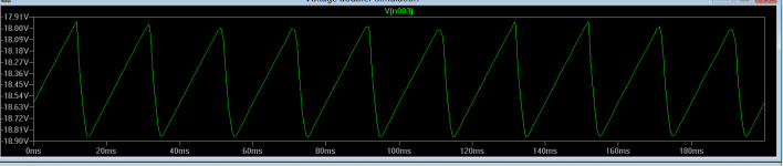
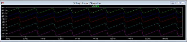
I had a voltage doubler sim already set up and so it only took a few snips and alterations to see how it behaves.
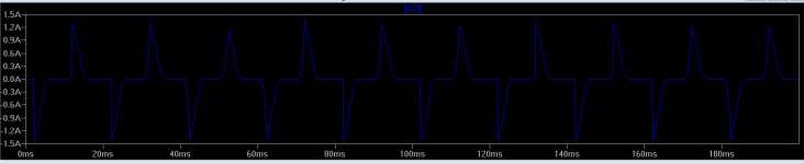
This would be the ripple across the 2200uf cap at around 120ma current draw. The current in the 470uf cap is pretty peaky. Increasing the value of that cap, even a little would obviate the need for a LDO reg. A 560 or 680uf would increase the unregulated rail enough but and its a big BUT... if the problem is really heat from the regs affecting everything, rather than the caps themselves sweating, then you have problems and the only fix would be to address the reg heatsinking to bring temperatures down.
This would be the ripple across the 2200uf cap at around 120ma current draw. The current in the 470uf cap is pretty peaky. Increasing the value of that cap, even a little would obviate the need for a LDO reg. A 560 or 680uf would increase the unregulated rail enough but and its a big BUT... if the problem is really heat from the regs affecting everything, rather than the caps themselves sweating, then you have problems and the only fix would be to address the reg heatsinking to bring temperatures down.
Attachments
It's also my understanding that increasing the cap values (as M-audio did) moves some of the heat to the regulators. .
Yes, increasing the 470uf gives the reg more headroom as the input voltage rises but as you say, that increase produces yet more heat from the reg.
I had a voltage doubler sim already set up and so it only took a few snips and alterations to see how it behaves.
This would be the ripple across the 2200uf cap at around 120ma current draw. The current in the 470uf cap is pretty peaky. Increasing the value of that cap, even a little would obviate the need for a LDO reg. A 560 or 680uf would increase the unregulated rail enough but and its a big BUT... if the problem is really heat from the regs affecting everything, rather than the caps themselves sweating, then you have problems and the only fix would be to address the reg heatsinking to bring temperatures down.
That was awesome, thanks! So since even 560uF would be too large to fit, I guess it must be why people recommend LDO regs.
You're welcome
You would need to look at the ripple on a scope to make a judgement on using an LDO. When the trough in each cycle of the ripple reaches the minimum voltage the reg can work with, is when problems start. So a LDO reg could help there if things were marginal.
You would need to look at the ripple on a scope to make a judgement on using an LDO. When the trough in each cycle of the ripple reaches the minimum voltage the reg can work with, is when problems start. So a LDO reg could help there if things were marginal.
Golly, look at D2 and D3 in the schematic attached to post#1. It appears to me, without prototyping it or running any simulations, that D2 conducts mega-amperes of current when the input falls below -0.8 volts, and D3 conducts mega-amperes of current when the input rises above +0.8 volts. That sounds dangerous to me.
- Status
- This old topic is closed. If you want to reopen this topic, contact a moderator using the "Report Post" button.
- Home
- Source & Line
- Digital Line Level
- Help with Delta 1010 PSU regs/diodes