Hello,
Ryanj, are populated boards also available? In this thread you mentioned they would be, but on that page for ordering are only bare pcbs. If they are available, what is the price?
Hi sl1,
I was originally intending to provide some populated and tested PCBs, but after much consideration I realised that I could not provide such a service for a reasonable price. So for now, unfortunately, that offer does not stand.
Ryan
The DCR of L1 and L3 are important . . . the use of inductors instead of resistors was to increase the effective reactance . . . as the 317 gain rolls off at around 10kHz the rising impedance of the chokes limits the amount of fall-off of CCS impedance at high frequencies.
First of all, thanks again for all of your work putting together this nice project. I know it's not easy to do something like this, especially given all the back seat driving that took place. I appreciate the clear explanation of your design choices. I suspected the use of an inductor in the current source was something like this. What wasn't clear to me was what happens to the reactance when the inductor is within the feedback loop of the LM317, which is effectively what happens when it's used to help set the current of an LM317 current source. Are the LM317 spice models good enough to simulate this?
TR1 was mainly there to make sure there was the correct polarity across C43 . . . C46 was originally intended as an alternative to the "CCS for AC" arrangement I had with C43 and L3 . . . there is plenty or room for experimenting/improvement in this area of the circuit.
If you wanted to get rid of the compensation cap . . . without the inductor in the L3 position, the circuit is stable without the added cap.
OK, now I understand how to set TR1. I hadn't understood that one needed to watch the bias on C43 but it makes sense once you explain it. Regarding the choice of a "CCS for AC" arrangement vs. conventional LM317, is this something you've experimented with in your builds? Or is this an exercise left for the reader. As always, it's interesting to hear others experience with these things.
All the best.
---Gary
You're very welcome Gary, I'm grateful that experienced guys at diyaudio like yourself have been interested enough to give it a go. So, thank you.First of all, thanks again for all of your work putting together this nice project.
Yeah, its definitely not easy, but at the same time it was a good experience. I hope some of the people following along got something out of it too.I know it's not easy to do something like this, especially given all the back seat driving that took place.
I searched around the net for the most accurate models I could find. The one I used was supposedly the most accurate of the 3 that I obtained. Just how accurate they are is hard to know as I have not got the gear to thoroughly test and compare. I did put a lot of faith into spice, probably more than I should have. But it saves a huge amount of time in testing prototypes, etc. In hindsight I should have spent a little more time on practical testing...Are the LM317 spice models good enough to simulate this?
Regarding the choice of a "CCS for AC" arrangement vs. conventional LM317, is this something you've experimented with in your builds? Or is this an exercise left for the reader. As always, it's interesting to hear others experience with these things.
No, unfortunately I didn't experiment enough to hear a difference. I would encourage anyone to experiment further. I would have liked to have taken some more noise measurements to compare the two different arrangements, but with the lack of a signal generator at the time it would have meant further investment. In the end I thought I would just give the option on the PCB for people to try both ways. If I had done another prototype this is probably the area in which I would have done some more work on, it obviously needs further attention, and is far from perfected. But with all its imperfections, im more than pleased with its overall performance.
Cheers,
Ryan
Paul Kelly on Australia Day
Hey Guys,
Just thought i'd upload "Paul Kelly - Dumb Things" for Australia Day!
Testing out JRiver outputting WASAPI to the WaveIO.
Paul Kelly - Dumb Things
Hey Guys,
Just thought i'd upload "Paul Kelly - Dumb Things" for Australia Day!
Testing out JRiver outputting WASAPI to the WaveIO.
Paul Kelly - Dumb Things
Hi Guys,
I've had a few enquiries about complete and tested Distinction-1541 v2 PCBs, so i've started a thread to get a list going.
Distinction-1541 v2 complete PCB interest list
Ryan
I've had a few enquiries about complete and tested Distinction-1541 v2 PCBs, so i've started a thread to get a list going.
Distinction-1541 v2 complete PCB interest list
Ryan
Oh its the same as the other thread.. sort of.
How much are the populated and tested DAC costing to the buyer?
Are they hand or wave soldered SMD parts?. If its ok to ask about the power supply - what is required to get it functioning?.
Thanks Bryan,
WW
Hi Shane Ceglar,
Populated PCB cost will depend on numbers.
If I get 10 orders I should be able to get the populated PCB cost down to around $180AUD.
For one off orders a cost of $220AUD.
PCBs will be hand soldered and tested.
Ryan
Useing jan did ens switching psu on the distinction PCB
Hi gents,
I see Jan DIddens switcher PSU is available in the DIY audio store, could this be modified to give the voltages to successfully drive this project ( or any other TDA 1541a?)
It's + 5 v and +\-15v so could the -15v be reduced to -5v ?.
That would be good if it provides enough current?
Regards
Johnny
Hi Johnny
My 2 cents, without doubt Jan's switchers are good but from
mucking around with the TDA for 2 yrs now, I dare tell you
that the TDA is very sensitive on regs used as well as caps
thats used to power the 3 supply lines be it mains or decoupling.
Do not ever think that by using super low noise, low impedance
regs will definately give u good sound. This I will leave it to you
to find out for yourself.
DAC PSU
HI Sumotan,..thanks for the reply
I was just wondering if it offers a good compromise (assumeing its up to the job)
dont think it could ever beat a linear PSU, but i sadly don't have the cash to spend on just a whim, but your points are noted, thank you.
regards
Johnny
HI Sumotan,..thanks for the reply
I was just wondering if it offers a good compromise (assumeing its up to the job)
dont think it could ever beat a linear PSU, but i sadly don't have the cash to spend on just a whim, but your points are noted, thank you.
regards
Johnny
Hi Shane Ceglar,
Populated PCB cost will depend on numbers.
If I get 10 orders I should be able to get the populated PCB cost down to around $180AUD.
For one off orders a cost of $220AUD.
PCBs will be hand soldered and tested.
Ryan
Hi ryan. I'm interested in getting one but might I suggest something for v3 if you ever do one. I'm talking purely for the analog outputs here, I'm happy with the connectors on the pcb for the digital inputs. I've used RP-SMA female sockets so that I can get a really good low impedance connection but also keep impedance at 75 ohm and use RG6 coax coming directly from the PCB into my amp. To preserve shielding and to keep correct impedance. I'm strange but I like to keep impedance correct even for audio signals. I figure that any digital noise which makes it into the analog side can then find a path to ground much easier. Make sense?

You could just put the holes required for the RP-SMA socket on the board and still have plenty of room? maybe... Wont even need to populate it with a socket, I'll gladly do that even on the populated pcbs. I can't tell you what to do. At least that way you can cover my use case and also give others who don't use coax for audio signals plenty of room for making a good solid connection.
Also. I'm not suprised that you preferred a SMPS psu over a battery, I've before tried these dacs with batteries and it sounded awful and stale, lifeless.
I personally prefer E-core transformers. They improve things a lot. Despite being 'technically' inferior.
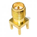
This is the RP-SMA sockets that I use on my analogmetric dac, I use RP-SMA female to RG6 coax connectors (crimped types) throughout my builds. I'm interested in getting one of your dacs but would LOVE it if V3 had large low ohm RP-SMA connectors on the analog outputs instead of those little solder tabs that are close together. I can then use small coax to run to an external AD797 opamp. See attached 1st pic:
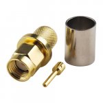
Also. I've attached a photo of the RP-SMA connectors for 75 ohm RG6, note the 2nd attached pic, the center pin is female, not male. It has a little hole in the center. I've found these connectors to be much easier to find than the other style (SMA) which I saw that you used in V1.
Differences of SMA and RP-SMA Connector FPV Antenna - Oscar Liang
Attachments
Last edited:
TDA 1541A transformer recomendation
hi ya boyz,
can anyone suggest a reasonabaly priced (but small) transformer to power this DAC +a aditional 5 V winding?--(thought about Jan Diddens Linear Switcher fom the DIY Audio shop )--but a good linear supply with low noise regs may be the only way to go in the long run?
I have an issue with space so i am looking for a small footprint for x former and regulators (hence my inital intrest with Jans linear switcher)
thanking you all
Johnny
hi ya boyz,
can anyone suggest a reasonabaly priced (but small) transformer to power this DAC +a aditional 5 V winding?--(thought about Jan Diddens Linear Switcher fom the DIY Audio shop
)--but a good linear supply with low noise regs may be the only way to go in the long run?I have an issue with space so i am looking for a small footprint for x former and regulators (hence my inital intrest with Jans linear switcher)
thanking you all
Johnny
Hi Ryan,
what do you think of IanCanada i2stopcm to use. with your pcb?
If correct, how would it connect? the outputs of Ian i2stopcm are:
Clk
Lllr
Dl
Dr
while the inputs of your pcb are:
Le/ws
Bck
Dl/D
Dr
thank you very much.
Hi Jjazz,
I've been using Ians pcbs for a while now with no complaints.
CLK --> BCK
LLLR --> LE/WS
DL --> DL/D
DR --> DR
You might want to also consider Pedjas "USB to simultaneous data or I2S converter, series 2, which also has simultaneous data output.
Ryan
hi ya boyz,
can anyone suggest a reasonabaly priced (but small) transformer to power this DAC +a aditional 5 V winding?--(thought about Jan Diddens Linear Switcher fom the DIY Audio shop
I have an issue with space so i am looking for a small footprint for x former and regulators (hence my inital intrest with Jans linear switcher)
thanking you all
Johnny
Hi Johnny,
I spoke to Jan about his silent switcher, and here's what he said:
"Hi Ryan,
Yes that is possible if you feed it from a USB charger or a PowerBank which also floats (which they normally are).
You can draw minimum 150 mA from the 30V.
The on/off switch is internally grounded but if you run the two wires to an isolated toggle switch that will also float then."
So as you can see it will be a mismatch with my PCB as it only takes 135mA and could not handle too much more voltage than 28V due to heat sinking restraints on the PCB.
One way around it would be to burn up a some power before my PCB, ie drop the voltage with a resistor, and also get the current up by paralleling a resistor with the circuit on my PCB. Or you could just pre-regulate with an LM317, and keep the the shunt resistor there to keep the current at 150mA.
Ryan
Jan's switcher
Hi Ryanj,
Thank you for talking to jan, I was think along similar lines to dropping the voltage for the DAC , i have space issues trying to cram it in to a small box based on a phillips pro 2 transport, though getting 12s out of it ti feed the DAC is easy.
I shall order a switcher when funds allow, how are you getting on with the populated PCB for the Mk 2 version!, guess I would have to purchase that first.
My thanks for all your hard work.
Johnny
Ryanj,
Oh wow! I found your Distinction DAC!!! So you're working on MK2 of the Distinction? I just posted on the SEN thread and was curious about what other TDA1541 threads and it's all here along the Ultimate NOS...
Is the MK2 version schematic the same as what was mentioned on the SEN thread that your working on?
Hi Ryanj,
Thank you for talking to jan, I was think along similar lines to dropping the voltage for the DAC , i have space issues trying to cram it in to a small box based on a phillips pro 2 transport, though getting 12s out of it ti feed the DAC is easy.
I shall order a switcher when funds allow, how are you getting on with the populated PCB for the Mk 2 version!, guess I would have to purchase that first.
My thanks for all your hard work.
Johnny
Hi Johnny,
No problem.
Just working on a few things before I put my offer on the table -hopefully within the next week.
Ryan
Ryanj,
Oh wow! I found your Distinction DAC!!! So you're working on MK2 of the Distinction? I just posted on the SEN thread and was curious about what other TDA1541 threads and it's all here along the Ultimate NOS...
Is the MK2 version schematic the same as what was mentioned on the SEN thread that your working on?
Hi fccn75,
The PCB im working on is a separate PCB that will have shunt regs, CCS, and a SEN circuit. Yes the schematic I posted was from this new design. Not sure if this PCB will be made avaliable or not, still a few areas where I would like to improve on. The main issue is thermal drifting on the output.
Ryan
- Status
- This old topic is closed. If you want to reopen this topic, contact a moderator using the "Report Post" button.
- Home
- Source & Line
- Digital Line Level
- TDA1541A Diy Pcb - "Distinction-1541 v2"