OK - I've got an interesting problem with a pair of Muse 'Mini PCM1793' DAC's - neither of the blessed little devices will lock on to, or decode, a bog-standard 16 bit, 44kHz, coaxial S/PDIF data stream.
Eh? WTF? "Over..."
Hmmm here's the 'Facts' and 'Data' that I currently believe are true:
Since two separate devices are failing in an identical fashion, suspect that there's an issue in system, setup, or user's brain:
1) Both devices can and will decode any data stream up to 96 kHz via the optical Toslink, and sound quite decent in the process.
2) Neither coax cabling (tried several types from 50 to 72 ohm) nor source device (tried Raspberry Pi with HiFiDigi board, Logitech Squeezebox, MiniDSP NanoDigi, and onboard Via audio S/PDIF coax) makes any difference - every Coaxial S/PDIF input fails on both boards
3) OTOH, a Firestone Audio PCM1794/DIR9001 - based 'Spitfire' DAC, a BB 1794/DIR9001 evaluation DAC board, and a cheapo 'FIIO' CS-based DAC - successfully decoded all of the presented SPDIF streams from 16/41 to 24/96 kHz with no issues.
So, I thought that it was pretty reasonable to conclude the following:
A) That my system is presenting acceptably clean S/PDIF signals which should be decoded by a functioning DAC, and both DACs fail under only one condition.
B) Since the DAC's failure mode is coax signals only, while Toslink signals decode correctly - I assume that everything from the PCM1793 chip onwards works, and that the problem is upstream in the DIR9001 receiver, the 74HC00 (four dual-input NAND gate) IC, or in the coax connector and passive components ahead of the PCM1793.
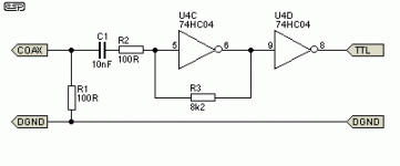
Since both my skill set and tools are very limited, please bear with me as I try to reason the board's switching logic out - hopefully there's a .PDF of a schematic attached to this message which should resemble the device under test so you can refer to it
As near as I can tell, switch K1-K2 pulls a logic-level line from high (Coax in) to low (Optical in) which appears to trigger the following cascade of events:
1. pins 12 & 13 go logic high, which should send pin 11 - NAND gate 4Y output low
2. 4Y is tied to pin 2 gate 2B input - which, if gate 2a input (pin 1 Coax input) is high should send pin 3 - gate 1Y high
3. The switch also puts logic high onto pin 5 gate 2B input - this should toggle gate 2Y's output to low - which it appears to do.
4. The actual pulse stream appears to be generated by gate 3, which should follow gate 1Y for coax input or gate 2Y for optical input - it presents at output 3Y (pin 8) is also present at resistor R9 (33 Ohm).
So far, this all appears to make sense, and should be a pretty straight forward switching arrangement, so I started dragging out my ancient test gear and magnifying lamp.
Troubleshooting - The obvious issues all test good:
I) There's DC continuity from the center pin of a coax cable to the input side of capacitor C4, so the input jack is good.
Ia) R1 measures 68 Ohms, so there should be roughly 72 ohms input impedance at audio frequencies
II) Logic high is present at switch K1, is correctly pulled low, and appears as expected at pins 5, 12, and 13.
III) There's 3.365 VDC at pin 14 of the 74HC00, and <1 ohm to ground at pin 7 - VCC is stable in both input modes.
Firing up our utterly untrusty Tek 545 (we bought it to scrap for the tubes & didn't have the heart to murder the poor 'scope) we see the following:
IV) The optical input looks like a square wave of approximately 1.5uS with .5V p-p, the coaxial input shows roughly the same waveform, but only .2V p-p.
V) The waveform that appears at resistor R9 closely follows the optical input, but is almost 1V p-p - its timing looks OK and it it is being correctly decoded.
VI) HOWEVER - when the coax is switched in, the 3Y output waveform stretches to 5mS and does not resemble the input waveform - looking more like a classic flip-flop signal.
VII) The coax waveform does appear at pin 9 with optical switched in, but disappears when the coax is switched in - and I cannot get a clean waveform from pin 1.
VII) One other anomaly to note, R2 in the schematic shows as 1M Ohm, but is actually a 720 Ohm resistor both by measurement and by color code.
My immediate temptation would be to simply lift one leg of R2, and see if the out of spec resistor is creating an R-C filter that is is just to low in frequency, instead of quenching spikes like 1M resistor should have done.
Otherwise should one suspect two defective 74HC00 chips? It doesn't seem likely that someone would counterfeit lowly IC logic chips - you'd be better off printing bogus Roubles, at least paper money has 'Sanitary Qualities' - while IC's are terribly sharp & painful when used this way...
All ideas and comment are appreciated - I'm somewhat stumped & the vendor is typically slightly difficult - although this doesn't look to be their issue but Muse's error.
Thanks & Cheers
Jim
Here's a link to the schematic I've been using - it seems to match well with the Muse board:
http://www.pic16.com/soft/PCM1793DAC_sch.pdf
Eh? WTF? "Over..."
Hmmm here's the 'Facts' and 'Data' that I currently believe are true:
Since two separate devices are failing in an identical fashion, suspect that there's an issue in system, setup, or user's brain:
1) Both devices can and will decode any data stream up to 96 kHz via the optical Toslink, and sound quite decent in the process.
2) Neither coax cabling (tried several types from 50 to 72 ohm) nor source device (tried Raspberry Pi with HiFiDigi board, Logitech Squeezebox, MiniDSP NanoDigi, and onboard Via audio S/PDIF coax) makes any difference - every Coaxial S/PDIF input fails on both boards
3) OTOH, a Firestone Audio PCM1794/DIR9001 - based 'Spitfire' DAC, a BB 1794/DIR9001 evaluation DAC board, and a cheapo 'FIIO' CS-based DAC - successfully decoded all of the presented SPDIF streams from 16/41 to 24/96 kHz with no issues.
So, I thought that it was pretty reasonable to conclude the following:
A) That my system is presenting acceptably clean S/PDIF signals which should be decoded by a functioning DAC, and both DACs fail under only one condition.
B) Since the DAC's failure mode is coax signals only, while Toslink signals decode correctly - I assume that everything from the PCM1793 chip onwards works, and that the problem is upstream in the DIR9001 receiver, the 74HC00 (four dual-input NAND gate) IC, or in the coax connector and passive components ahead of the PCM1793.
Since both my skill set and tools are very limited, please bear with me as I try to reason the board's switching logic out - hopefully there's a .PDF of a schematic attached to this message which should resemble the device under test so you can refer to it
As near as I can tell, switch K1-K2 pulls a logic-level line from high (Coax in) to low (Optical in) which appears to trigger the following cascade of events:
1. pins 12 & 13 go logic high, which should send pin 11 - NAND gate 4Y output low
2. 4Y is tied to pin 2 gate 2B input - which, if gate 2a input (pin 1 Coax input) is high should send pin 3 - gate 1Y high
3. The switch also puts logic high onto pin 5 gate 2B input - this should toggle gate 2Y's output to low - which it appears to do.
4. The actual pulse stream appears to be generated by gate 3, which should follow gate 1Y for coax input or gate 2Y for optical input - it presents at output 3Y (pin 8) is also present at resistor R9 (33 Ohm).
So far, this all appears to make sense, and should be a pretty straight forward switching arrangement, so I started dragging out my ancient test gear and magnifying lamp.
Troubleshooting - The obvious issues all test good:
I) There's DC continuity from the center pin of a coax cable to the input side of capacitor C4, so the input jack is good.
Ia) R1 measures 68 Ohms, so there should be roughly 72 ohms input impedance at audio frequencies
II) Logic high is present at switch K1, is correctly pulled low, and appears as expected at pins 5, 12, and 13.
III) There's 3.365 VDC at pin 14 of the 74HC00, and <1 ohm to ground at pin 7 - VCC is stable in both input modes.
Firing up our utterly untrusty Tek 545 (we bought it to scrap for the tubes & didn't have the heart to murder the poor 'scope) we see the following:
IV) The optical input looks like a square wave of approximately 1.5uS with .5V p-p, the coaxial input shows roughly the same waveform, but only .2V p-p.
V) The waveform that appears at resistor R9 closely follows the optical input, but is almost 1V p-p - its timing looks OK and it it is being correctly decoded.
VI) HOWEVER - when the coax is switched in, the 3Y output waveform stretches to 5mS and does not resemble the input waveform - looking more like a classic flip-flop signal.
VII) The coax waveform does appear at pin 9 with optical switched in, but disappears when the coax is switched in - and I cannot get a clean waveform from pin 1.
VII) One other anomaly to note, R2 in the schematic shows as 1M Ohm, but is actually a 720 Ohm resistor both by measurement and by color code.
My immediate temptation would be to simply lift one leg of R2, and see if the out of spec resistor is creating an R-C filter that is is just to low in frequency, instead of quenching spikes like 1M resistor should have done.
Otherwise should one suspect two defective 74HC00 chips? It doesn't seem likely that someone would counterfeit lowly IC logic chips - you'd be better off printing bogus Roubles, at least paper money has 'Sanitary Qualities' - while IC's are terribly sharp & painful when used this way...
All ideas and comment are appreciated - I'm somewhat stumped & the vendor is typically slightly difficult - although this doesn't look to be their issue but Muse's error.
Thanks & Cheers
Jim
Here's a link to the schematic I've been using - it seems to match well with the Muse board:
http://www.pic16.com/soft/PCM1793DAC_sch.pdf
Last edited:
Har-umph! Over a hundred views, but no replies - should I shower before posting?
Quick status update:
A friend pointed out that I had unintentionally slighted the DAC's vendor - yes, it is a bit hard to deal with them, but not because they're a bad or ineffective supplier - actually, they've been pretty responsive.
However, there's a 12 hour time difference between us, a significant language barrier, shipping in/out of the PRC can take a VERY long time - and we're talking about roughly $100USD worth of goods - not worth going to great lengths for. We've an email sent to the vendor and are waiting for their response.
Sadly, the schematic that I've been using is similar, but not identical to the boards in hand - the topology seems about right, but there are differences in layout and part values between the Muse and the HiFiDIY.net versions. Tried to contact Muse-Audio, but all of their website's support and contact links seem broken in several browsers - sent an email to their order line & we'll see what happens.
In the meantime I'll create another post with more information and actual pictures
Cheers
Jim
Further info
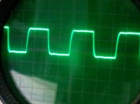
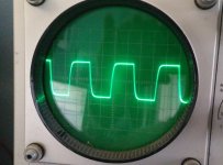
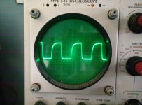
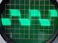
As promised here are some poor-quality 'scope pictures of an dead-stock unmodified board:
1st pic is the raw coaxial input data taken from the RCA input with the optical input selected - roughly 7.5mS, .3V p-to-p - looks clean enough...
2nd pic is Optical input data taken from the back of the TosLink receiver in optical mode - 7.5mS, 2.75V p-to-p, also clean...
3rd pic is the 74HC00's output signal in Optical mode at resistor R9, which feeds the DIR9001's RXIN pin....slightly skewed. but still acceptable at roughly 7.4mS, 3V p-to-p.
4th pic is the coax input signal in coax input mode - last time I saw this much jitter was at the local Unofficial Peruvian Importer's Convention & we were all very well armed...
One hopes that this might jog loose a thought or two from the assembled multitude...
Thanks & cheers
Jim
Attachments
I don't see a problem with the circuit. Personally, I would lift on side of R2, the "bottom" side of R5 (as viewed in the schematic) and the "left" side of R9. I would then connect the top of R5 to the left of R9 to bypass the 7400 completely.
Thanks Tyler -
It appears that we might share a common-rail brain, I'd been mulling over a similar idea, and popped C8 free from the board, which disabled the optical input - although I'm not certain that this was necessary - then lifted the output leg of C1 and tied it to the input side of of R9 thinking that this would bypass the 7400.
It does bypass the 7400, but a smarter person would have remembered that the 100K resistor plays a role in this tragedy too - DOH! I'll solder a 100K inline this evening and report back.
And do be careful out there, remember that the next step after Red Shift is Purple Haze....

Cheers
Jim
Quick update -
Tried bypassing the 7400 by passing the incoming S/PDIF through a 104 coupling cap, a 100K resistor and then directly to Pin 20 of the DIR9001 (RXIN) - no joy, it's still throwing an unlock error.
I left the 68 ohm resistor to ground, since I'm assuming that it's needed to properly terminate the 72 ohm coax.
But all this fussing about got me to thinking that one of differences between Toslink and Coax as an S/PDIF physical transport layer is that Toslink provides electrical isolation between the source and receiving devices.
I wonder if theres a ground /ground loop/ garbage injection issue that's preventing either 7400 from 'seeing' the high-low signal transitions or if there's so much jitter and phase shift that the DIR9001 cant lock?
All of the DACs that will lock onto the coax signal are either transformer coupled (1794 Eval board, Firestone Spitfire) and have linear PS's - or are on 5VDc USB wall warts which are pretty indifferent to their environment and use coupling caps (FiioTaishan).
Tried swapping power supplies and PS plug orientations - no joy either. I'll try to see if there's any discernible DC or AC offset between the source and the muse boards and also look to see if there's a noise component I've missed.
One of the other threads about this class of PCM1793 miniDACs mentioned that they use one of the three-tab devices to split VCC into positive and negative legs referenced to an artificial ground.
I'm wondering if a defect in this splitter arrangement would lead to an 'unbalanced' situation in the digital Vcc+/Vcc- lines?
If there was an unbalanced condition, then the stronger Toslink signal might be enough above the threshold to be detectable, while the weaker coax signal would be glitched by noise.
There are entire moments when I believe that I know what's happening here - then I realize that this is merely another effect of profound ignorance.
<SIGH!>
Jim
I don't think that the 74HC00 is defective. But it is not the best device for the job either. There could be two problems:
1. The gain is far too high. An unbuffered 74HCU04 would have been better.
2. With a supply voltage of 3.3V it is relatively slow.
The way R2 is connected in the schematic it should definitely not be 720 ohm. I would connect it in series with C1 instead of connecting it to ground. In that case 720 ohm could be OK. If R2 was 1M, and connected to ground, it would create a small offset, which could avoid problems with sensitivity to noise with no input and perhaps oscillations.
The SPDIF level seems to be a bit on the low side. It should normally be 0.5V pp. With a proper input I would expect it to work though.
The jitter you have in the last picture is definitely bad. Is there a missing ground connection somewhere?
Well, checked the voltage potential between the supplied 12VDC power supply and the coaxial S/PDIF ground (e.g. coax shield) on several devices and while there's negligible DC offset, all three devices (Squeezebox Touch, FIIO DAC, Computer RCA out) shoed between 23.7 and 24.6 VAC potential between the 'grounds.'
Think that might have an effect?
Mutter, mutter, mutter ....
For giggles we also checked the Vcc 6.17VDC, Vee -6.67VDC, V5A 4.99VDC, andVD3.3 3.31VDC voltages - apart from the offset between Vcc and Vee, they seem OK.
BTW, is it common practice to use an audio amplifier chip (LM8517) as a voltage source, or was someone just clever with this circuit?
Cheers
Jim
Using an op-amp as a rail splitter is not uncommen.
Regarding the SPDIF I think the problem is mainly R2.
Jens -
Thanks for the comments, I was puzzled that they used a chip which I think of as a low-power audio amp in place of an op-amp, but if you consider the LM1875 as a a relatively high-power op-amp with some extra protection features - it makes sense, especially if they're available very cheaply.
One thing that I've not made clear is that I bought two Mini PCM1794's - so one is kept box-stock, while I putter and fuss about with the other one - it helps me to have a known, stable reference point.
So one board is fairly close to the schematic attached to the first post, and the 2nd board has been modified so that coax input now goes through a 104 coupling cap and then directly to resistor R9 (33ohm) - I'm not using a 100K resistor because I see no signal behind it in the path.
With just the DC blocking cap, I see a pretty clean .5V p-p square wave of roughly 5ms duration at r33 - I can also see the same signal at pin 20 (RXIN) of the DIR9001, and it still looks good.
Still no lock - I traced the AC offset I was seeing to a blown MOV in my power strip, and now there's a much more typical 1.3 VAC differential between the grounds which I can live with.
[MERDE] RTFM, Jim...! Looking at the data sheet, RXIN is a TTL input with a minimum 2Vp-p drive requirement - no wonder it spits up at .5 V - sigh!
So, back to square one - trying to understand why the 7400 isn't triggering....
Cheers
Jim
Hi Jim,
If you take the signal directly to the DIR9001 I would suggest to feed it with a 0 to 3.3V signal. There should be no capacitor in series with the input. Just the 33 ohm. An the 75 ohm on the input and the 74HC00 should of course also be removed.
Interesting that the two PCB's were delivered with different configurations! Unless you asked them to it could indicate that the supplier is not too reliable.
If you want to input an SPDIF signal you need the 74HC00, the series capacitor, a resistor, e.g. 720 ohm in series with the capacitor and the 100 kohm feedback resistor (to get a controlled DC operating point). And a 75 ohm resistor on the input. You could probably keep R2 at 1 Mohm to avoid potential problems with noise, when no signal is applied.
Jens
coaxial S/PDIF now functions
With thanks to JensH who very kindly and patiently brow-beat me into following the path to resolve this issue - the Muse PCM1793 DACs are now correctly decoding S/PDIF coaxial signals.
As near as I can tell, both boards have defective 74HC00 chips, all of the passive components in the signal path appear to be roughly the correct values and are installed in the marked locations, but the signal coming out of the 7400 with coax selected is garbage.
So, following Jens' advice, I lifted the 33 ohm resistor that feeds the RXIN pin of the DIR9001 receiver, and slavishly following the attached schematic, I built an coax input circuit to bypass the Muse board's defective one.
Much to my horror the blessed blob of bugs works - although it looks like a reject from a Stalinist trade school.
This was a stupid amount of effort for a marginal result, but it's been an interesting way to blow off some cobwebs and excercise my vocabulary.
I'll complain to the vendor, but won't expect much in return, at least they'll know that there's a problem and perhaps the next poor fool won't have to spend so many head-scratching hours
Cheers and thanks to everyone
Jim
Attachments
- Status
- This old topic is closed. If you want to reopen this topic, contact a moderator using the "Report Post" button.
- Home
- Source & Line
- Digital Line Level
- S/PDIF problems Muse Mini PCM 1793 DAC