Well one can choose to make it 2kHz. In some sense the 22,05 is fixed but you could back down to say 18kHz if 20 isn't sacred to you 🙂
But I do agree - where its done is not so important.
//
But I do agree - where its done is not so important.
//
Well one can choose to make it 2kHz. In some sense the 22,05 is fixed but you could back down to say 18kHz if 20 isn't sacred to you 🙂
But I do agree - where its done is not so important.
//
Point is that you still face the same issues of selecting which frequencies and type of filter is used to remove (or not) the images whether you filter on computer or in FPGA.
The other thing is that the recommendation to use PC-based applications to upsample on the fly on a computer assumes that everyone is using a computer as their only source, which is not always the case.
20kHz, 18kHz, 16kHz, 14kHz - pick your poison. 😉
I've been reading Peter Cravens papers on Apodizing filters and the assumption is that frequency should be at worst less than .1dB down at 20kHz. That is one approach I guess.
Last edited:
He musts have very good hearing.
//
Sorry ±0.2dB, but this was discussing higher sampling rates where it's easier to pull off.
This quote is from Craven's "Controlled pre-response antialias filters for use at 96kHz and 192kHz" AES paper.
Traditional filter design has been either minimum phase or linear phase. A minimum phase filter has a monotonically increasing impulse response prior to the main peak, all downswings occurring afterwards. A linear phase filter has a symmetrical impulse response, so that in the maximally flat case there must be at least one downswing prior to the main peak. Thus, there is tension between the desire for a linear phase response in the audio frequency region, and a desire to avoid pre-responses in the time domain.
Does an antialias filter’s frequency response need to be strictly limited? We have assumed that the response at the Nyquist frequency should be down by 80dB or more, so that alias artefacts will be down by at least this amount. We do not comment on whether this is psychoacoustically necessary, indeed in [1] we see that some consider that it may be better to allow some aliassing in order to have a filter with a wider transition bandwidth and a ‘tighter’ time response.
How flat does the frequency response need to be in the range 0–20kHz ? Some contributors to [1] are prepared to contemplate a droop of 1–2dB at 16kHz. Here we will assume that a slow variation of ±0.2dB in the amplitude response over 0–20kHzwill be acceptable.
Essentially I agree, but I think there are two things that need to be expressed more carefully:Regardless of where it is done you have to deal with the imaged generated by resampling at some point.
Any kind of upsampling or oversampling of 44.1kHz still has a 2.05kHz transition band between the audio band and fs/2.
The DAM basically does in the FPGA what HQ Player does in software.
The images of the <20kHz spectrum are not "generated by resampling". They are a property of a signal sampled with 44.1kHz. Even with no resampling (so with a 44.1kHz DAC) you will have the images, but here they are at the analog output and can only be handled by analog filtering. The advantage of resampling with a higher frequency , is that the first images now also appear on the digital side and can be treated with digital filtering.
The first image comes mirrored in the frequency domain so at 44.1-20 kHz
(see e.g. http://www.dspguide.com/CH3.PDF), so you have a 4.1kHz transition band. This of cause only applies if, at time of recording, the signal was properly filtered so that there are no signal components above 20kHz.
If the recording engineer was a friend of slow filters you have a signal in the "transition band" which might call for a faster filter.
Last edited:
The first image comes mirrored in the frequency domain so at 44.1-20 kHz
(see e.g. http://www.dspguide.com/CH3.PDF), so you have a 4.1kHz transition band. This of cause only applies if, at time of recording, the signal was properly filtered so that there are no signal components above 20kHz.
If the recording engineer was a friend of slow filters you have a signal in the "transition band" which might call for a faster filter.
I've checked a selection of my CD rips, and they ALL have content above 20kHz, most to at least 21kHz and some right through to 22kHz, so I suspect it's actually fairly widespread.
see attached screen shots from a track called Stopover Bombay by Alice Coltrane. Sorry about the different zoom levels.
It is pretty low level but it is there.
Attachments


Last edited:
If the recording engineer was a friend of slow filters you have a signal in the "transition band" which might call for a faster filter.
No recording engineer I know does filtering up there by default, only if audible problems occur, so I would guess most recordings have some signal in the transition band.
But the AD converter with its filter should take care of that also.
I've checked a selection of my CD rips, and they ALL have content above 20kHz, most to at least 21kHz and some right through to 22kHz, so I suspect it's actually fairly widespread.
see attached screen shots from a track called Stopover Bombay by Alice Coltrane. Sorry about the different zoom levels.
It is pretty low level but it is there.
No recording engineer I know does filtering up there by default, only if audible problems occur, so I would guess most recordings have some signal in the transition band.
But the AD converter with its filter should take care of that also.
I see no real problems. All I wanted to say is,
if there is a x-dB signal at 22kHz, there will be a x-dB signal at 22.1kHz.
If you do not care about the 22kHz signal you design a filter, as before, with transition band of, say, 20-...kHz, and you are fine. If you are a believer of the importance of the 22kHz component and want to transmit it unatenuted ... you have to design with a much smaler transition band.
Before recording (or converting) to a 44.1kHz signal you have to ensure that there are no (or only very weak) components above the Nyqvist frequency 22.05kHz (or at least above 44.1kHz - f, where f is your desired later passband frequency) as they will result in aliases, which are later (with playback filtering) uncorrectable errors in the recorded signal.
So filtering (at recording) is only not needed if the signal does not contains such high frequency components anyhow.
Recording with higher frequencies, eases life as you need only to take care of much higher frequencies with (analog) filtering (usually the microphone bandwidth will already be the filter) and can later (if needed) do digital filtering before sample rate conversion (e.g. for CD pressing).
Last edited:
Ok...
So I now understand why the NOS filter sounds harsh 🙂
This means that the NOS filter files need to be altered so there is no gain applied to any filter that has a bypass setting. The trade off is that level will be low and the DAC will clip if you set the gain any higher than V+00.
Paul, did you ever go back and alter the NOS file posted?
I am a little confused about FIR2, is it also bypassed/upsampling by the NOS file or is it still active? What is it doing if it is not bypassed?
Paul, did you ever go back and alter the NOS file posted?
I did, but haven't listened to it as yet.
This is basically a "full bypass" in that all filters except the 2 for cd de-emphasis are set to a single coefficient of 1.000 and a gain of 1.
cheers
Paul
Attachments
I am a little confused about FIR2, is it also bypassed/upsampling by the NOS file or is it still active? What is it doing if it is not bypassed?
It wasn't bypassed in the previous version. FIR2 is set well above audio - both are flat out to 100kHz and is -80dB by either 220/240kHz.
I've attached a few screenshots of the first 60 seconds of Miles Davis's "So What".
First is a straight rip from CD:
Second is up sampled x 8 with no FIR filtering applied:
Third is a basic linear phase FIR filter. You can see images of the sub-2kHz audio mirroring. These images are around -80 to -90dBFS.
Attachments


continuing...
Next one is upsampling x8 of the upsampled x8 SoWhat, with no filtering applied:
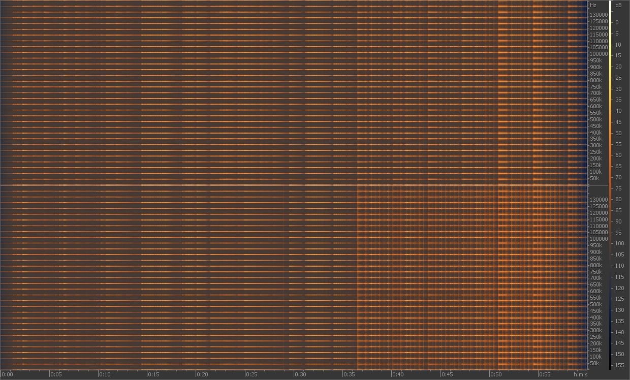
And as above with only FIR2 filter applied
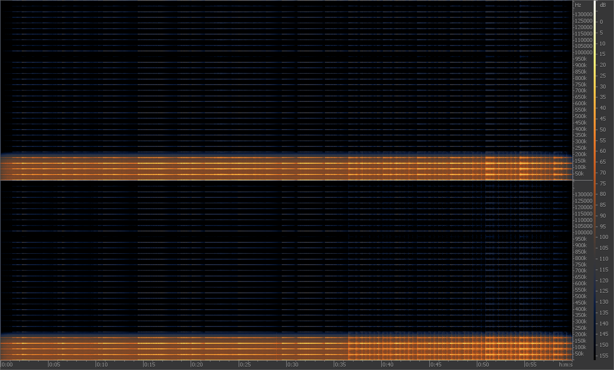
The analog filter at the DAC output has a corner frequency of 212kHz so this is not what you see at the output terminals. Even so it should illustrate with the 2 tiers of FIRs are doing in conjunction with up/over sampling.
Next one is upsampling x8 of the upsampled x8 SoWhat, with no filtering applied:
And as above with only FIR2 filter applied
The analog filter at the DAC output has a corner frequency of 212kHz so this is not what you see at the output terminals. Even so it should illustrate with the 2 tiers of FIRs are doing in conjunction with up/over sampling.
Attachments


Last edited:
I did, but haven't listened to it as yet.
This is basically a "full bypass" in that all filters except the 2 for cd de-emphasis are set to a single coefficient of 1.000 and a gain of 1.
cheers
Paul
Thanks for providing it. Shall listen to it. I am going through the available filters one by one. Fun stuff.
spzzzzkt, are these measuremnts on the analog outputs or analysis/simulation of the digital domain?
//
//
spzzzzkt, are these measuremnts on the analog outputs or analysis/simulation of the digital domain?
//
Digital domain.
see http://www.diyaudio.com/forums/digi...filter-brewing-soekris-r2r-3.html#post4229609
Stage 1:
Code:
sox /path/to/input.wav -b 24 -r 352.8k /path/to/upsampled_output.wav upsample 8 \
[fir /path/to/fir1_coefficents.txt vol 8]
Stage 2:
Code:
sox /path/to/upsampled_output.wav -r 2822.4k /path/to/final_output.wav upsample 8 \
[fir /path/to/fir2_coefficents.txt vol 8]
Purpose is to visualise the cascading effect of FIR1 and FIR2 not to analyse the DAC output, as the question posed was "what is the purpose of the FIR2 filter?"
Last edited:
I did, but haven't listened to it as yet.
This is basically a "full bypass" in that all filters except the 2 for cd de-emphasis are set to a single coefficient of 1.000 and a gain of 1.
cheers
Paul
Paul, I've loaded this twice and both times the volume is very low - at V00 it's just audible.
Paul, I've loaded this twice and both times the volume is very low - at V00 it's just audible.
I guess you must be running SE or unbuffered.
Yes it is quiet, but you did ask to listen to NOS for both filters with gain multipliers set to avoid adding distortion 😉
Upsampling x8 in the DAM is done by inserting 7 zero values between each pair of samples. This means that the energy of the original audio is reduced to 1/8th of the original, or -18dB.
Because NOS retains the 7 mirror images the total energy in the data is the same as the original audio but you can only hear the energy within the audio band. Adding gain to the x8 up sampled and unfiltered audio data will cause data to exceed 0dBFS - in other words it will clip.
There is a bit of wiggle room because Søren has said that the processing done in the FPGA has 2-4 bits headroom. As we don't know which applies under what circumstances we have to assume the lower figure is going to be relatively safe.
1 bit allows double the amplitude of a signal or 6dB gain, 2 bits allows x4 the amplitude or 12dB gain, and 3 bit allow x8 amplitude or 18dB gain.
You possibly see from this how the multiplier is used in the DAM filter configuration, and why the x8 oversampled settings which reduce energy in the filtered file to 1/8th the original require the data to be multiplied by 8.
Anyway back to the NOS.
This is the filter config for the too quiet "double bypass NOS"
Code:
dam1021,44100,8,1,1,1
Input FIR, 44.1 Khz Samplerate, Bypass
1.000

dam1021,48000,8,1,1,1
Input FIR, 48 Khz Samplerate, Bypass
1.000

dam1021,88200,4,1,1,1
Input FIR, 88.2 Khz Samplerate, Bypass
1.000

dam1021,96000,4,1,1,1
Input FIR, 96 Khz Samplerate, Bypass
1.000

dam1021,176400,2,1,1,1
Input FIR, 176.4 Khz Samplerate, Bypass
1.000

dam1021,192000,2,1,1,1
Input FIR, 192 Khz Samplerate, Bypass
1.000

dam1021,352800,1,1,1,1
Input FIR, 352.8 Khz Samplerate, Bypass
1.000

dam1021,384000,1,1,1,1
Input FIR, 384 Khz Samplerate, Bypass
1.000

dam1021,384000,8,2,1,1
Final FIR, 384 Khz Samplerate, Bypass
1.000

dam1021,352800,8,2,1,1
Final FIR, 352 Khz Samplerate, Bypass
1.000

dam1021,352800,8,30,5,1
Deemphasis IIR, 352.8 Khz Samplerate 50/15 uS
0.3533735087400593
-0.6245393735573087
0.2759469933909753
1.8617085892222387
-0.8664897177959644

dam1021,384000,8,30,5,1
Deemphasis IIR, 384 Khz Samplerate 50/15 uS
0.3520148312325706
-0.6284427828676498
0.2804855763857754
1.8726010243259992
-0.8766586490766952
I suspect that to avoid issues at higher bit rates the gain will have to be distributed between the fir1 and fir2. I will have to clarify the range of headroom with Søren...
The mods below add 6dB gain at FIR1 and 6dB at FIR2.
You'll have to test this for yourself and there is no guarantee it will not clip.
Code:
dam1021,44100,8,1,1,2
Input FIR, 44.1 Khz Samplerate, Bypass
1.000

dam1021,48000,8,1,1,2
Input FIR, 48 Khz Samplerate, Bypass
1.000
Code:
dam1021,384000,8,2,1,2
Final FIR, 384 Khz Samplerate, Bypass
1.000

dam1021,352800,8,2,1,2
Final FIR, 352 Khz Samplerate, Bypass
1.000
cheers
Paul
Attachments
- Home
- Source & Line
- Digital Line Level
- Filter brewing for the Soekris R2R