Filters and buffers
In post 115 I put up a picture of the built up board containing the two filters - the one I've called the 'quasi elliptic' and the one you've already built (which does NOS droop correction). Post 119 shows the schematics for those filters yep. But point (5) here was about the I/V stage - so far I've not posted up a schematic for that, so that's on my to-do list. I'll examine what I've got (I don't even recall drawing myself a schematic) when I do a photoshoot - the transistors for this I mounted on the underside of the board, close to the DACs. I used BC807-40s, one per phase, total 4 transistors.
That's correct.
Input is to the left - going to the transistor (an EF) base via L7 (a ferrite bead). Yes bottom right is negative supply and top right is positive. That just leaves the output which is in the middle, coming via the second ferrite bead (L8) from the emitter of the EF. I think I'm using +8 and -8V for the supplies since I reduced the shunts' settings.
Yep.
The input is top right - R63 is the I/V resistor - the top of it goes to the collector of the I/V transistor. Output to buffers comes from the top of the other 1070 ohm resistor (R64). Probably 1100 ohms is close enough for these two Rs, given that the inductors are at best 10% tolerance. For the caps I recommend NP0 SMT but I'm guessing you'd prefer leaded? In which case choose polypropylene types for lowest loss.
I believe this is what you pictured in post #115 on page 12, and subsequently provided a schematic for in post #119 on page 12, correct?
In post 115 I put up a picture of the built up board containing the two filters - the one I've called the 'quasi elliptic' and the one you've already built (which does NOS droop correction). Post 119 shows the schematics for those filters yep. But point (5) here was about the I/V stage - so far I've not posted up a schematic for that, so that's on my to-do list. I'll examine what I've got (I don't even recall drawing myself a schematic) when I do a photoshoot - the transistors for this I mounted on the underside of the board, close to the DACs. I used BC807-40s, one per phase, total 4 transistors.
And the classA buffer is shown in post #126 on page 13.
That's correct.
I need some help putting the pieces together. The classA buffer has three lines on the right and one on the left. What does each line correspond to? I'm assuming bottom right is negative supply? Then I believe there's input (from AA filter), positive supply, and output (to NOS droop filter), not sure which line they correspond to...
Input is to the left - going to the transistor (an EF) base via L7 (a ferrite bead). Yes bottom right is negative supply and top right is positive. That just leaves the output which is in the middle, coming via the second ferrite bead (L8) from the emitter of the EF. I think I'm using +8 and -8V for the supplies since I reduced the shunts' settings.
For the NOS droop filter, I believe the two lines on the right correspond to the + and - signal from the buffers. And the two lines on the left would either (1) need a series cap for DC-blocking if the amp accepts differential inputs, or (2) connect to the custom transformer for balanced-SE conversion. Does that sound right?
Yep.
Lastly, for the AA filter, where are the inputs (from DAC ICs) and outputs (to classA buffer)?
The input is top right - R63 is the I/V resistor - the top of it goes to the collector of the I/V transistor. Output to buffers comes from the top of the other 1070 ohm resistor (R64). Probably 1100 ohms is close enough for these two Rs, given that the inductors are at best 10% tolerance. For the caps I recommend NP0 SMT but I'm guessing you'd prefer leaded? In which case choose polypropylene types for lowest loss.
Hi Fellows,
Played a bit with opamps today.
Prior to that I add that it's all feeling, no truth at all but the way these ICs behave in my system and the way my brain compute the datas from psycho and ears inputs.
I think that after removing 4 DACs and fitted the filter the DAC sounds less like a boombox in bottom and got much more presence in highs. From dark and overly muddy in bottom to straight.
That being said, the AD845 does not fit my tastes. I feel it lacks power in drum's toms, some dynamic is missing, something I don't like.
The OPA602 is good and boring,
the LM6171 shows great details in mids and relaxed, rolled off slightly at both ends. BTW it was in the taste of a friend wich likes velvet backroom sound (if that makes sens for someone...).
And the winners are:
AD844 wich I like more that AD845 (psycho-acoustics?), right now playing, and the LT1028 wich I need to live with one week to see if I really find them the best. The only problem is that I ran the LT1028 with a 10pf cap in the feedback and they still makes that "FM birdies" sound, slightly but there. I think I'll try my 47pf ceramics or even 100pf polystyrenes. Or just try to dig a bit more in the datasheet")
Any other competitor you guys can advise? Or share opposite experiences?
Played a bit with opamps today.
Prior to that I add that it's all feeling, no truth at all but the way these ICs behave in my system and the way my brain compute the datas from psycho and ears inputs.
I think that after removing 4 DACs and fitted the filter the DAC sounds less like a boombox in bottom and got much more presence in highs. From dark and overly muddy in bottom to straight.
That being said, the AD845 does not fit my tastes. I feel it lacks power in drum's toms, some dynamic is missing, something I don't like.
The OPA602 is good and boring,
the LM6171 shows great details in mids and relaxed, rolled off slightly at both ends. BTW it was in the taste of a friend wich likes velvet backroom sound (if that makes sens for someone...).
And the winners are:
AD844 wich I like more that AD845 (psycho-acoustics?), right now playing, and the LT1028 wich I need to live with one week to see if I really find them the best. The only problem is that I ran the LT1028 with a 10pf cap in the feedback and they still makes that "FM birdies" sound, slightly but there. I think I'll try my 47pf ceramics or even 100pf polystyrenes. Or just try to dig a bit more in the datasheet
Any other competitor you guys can advise? Or share opposite experiences?
Last edited:
yes
Yes but the package is too small (maximum 100 mW ) high instant currents is present when you have one or more current source connected to the same output
Try to make a small aluminium dissipation connected to gnd and hear the results..
No, the dissipation of the TDA1387 is low - around 30mW when fed with 5V. Perhaps you're confusing it with the TDA1543?
Given the datasheet thermal impedance of 210K/W the typical power dissipation of 27.5mW gives a temperature rise for the die above ambient under 6oC.
Yes but the package is too small (maximum 100 mW ) high instant currents is present when you have one or more current source connected to the same output
Try to make a small aluminium dissipation connected to gnd and hear the results..
SOS: Save Our Silicon!
Hi Gumo,
I keep this idea in mind for next mod/fix if any.
Matt, what was the original opamp in yours? If you -still- have the LT1028 give it a try. But not now…
In my case; (passive 10K attenuator, 4 DACs, Epcos MKT 4.7µF coupling caps) and in their state (10pF at compensation pin (5) and 47pF at feedback network) these opamps are just the best. By far.
Question of taste I guess (they sound... nothing or staight?) but they are much more dynamic than others while being cleaner. But I favor dynamic (life as I feel it) first.
Now the problems (I wish it worked at first, but no, it does not and that annoys me to death).
First I have a 50hz hum on the left channel, never mind the opamp. How that can be on one channel as the two share the same supplies? The case or something? It is too loud for me to listen to this DAC, organ works are unlistenable.
- any way to remove it? I must remove it. And I have no idea of were it can come from :’( Ground loop? Where sould I cut?
Second, after a listening time of rock at moderate level I went to gentle music and noticed that the right channel’s LT1028 crackled. Digital silence shown no noise at all. But record's silence are terrible! Being scared that my precccciousssssss gears will vanish in smoke I’ve turned all off. My hand on the DACs’ case found it very hot. After a while I've moved both LT1028s to other channels. The same, very quicly the noises are on the right channel, so not an IC. AD844 back then: dead silent (but the 50hz hum of course). LT1028 back? Noises on the right channel. Now AD844 are in, boring but working.
- is a channel, not the other, just one, able to upset only the LT2018 opamp? Is it even possible? Or, even if the FM birdies when no-cap are gone, it still is oscillating on that right channel? Why? Worth trying the DIP package I have? (and sadly no more 47pF caps, so larger polystyrene 100pf and no compensating cap).
I’m lost, I was so happy with that LT1028 sound but that hum and worst the right channel’s rice frying noise… ='(
help!
Matt, what was the original opamp in yours? If you -still- have the LT1028 give it a try. But not now…
All three of mine came with the NE5534. At least in stock form these sounded pretty lousy. The AD845s Abraxalito recommended were immediately better. I've been waiting to see if others comment on their opamp rolling experiences, as many of the higher-end ones are kind of pricey.
You can avoid the opamps all together if you do Abraxalito's "next-gen" modification, which involves a DIY transistor-based I/V stage. Still planning on doing that soon as Abraxalito's willing to post the schematic.

As to your issues... unfortunately my experience is too limited to offer any suggestions except the most trivial/basic. If the case feels uncomfortably hot to you, I don't see how it can hurt to try running it completely removed from the case. Or, at least with the top cover removed. Mine no longer has any chance of going back in the case, so it's literally just an exposed board sitting (upside-down) on my desk. I used to have an IRS2092-based amp that kept having over-heating problems that resulted in sound quality problems (not exactly like yours, but I'm assuming many electrical components' behaviors are undefined when safe operating temperature is exceeded).
Another random thought: my tda1387 8x DAC has displayed unusual single-channel degradation on a couple occasions. One was when I think I shorted something when sliding the card back into the case. Not sure if that's the real reason, but when I more carefully re-seated the card, the problem went away. The other instance was when the mains cable wasn't fully seated. (And in hindsight, the first problem could have also been caused by the AC cable too I suppose.)
The only other thing: looking at your picture where you re-routed the RCA grounds: it looks like me like you scraped away the PCB laminate to expose the grounding layer, and soldered to that? Any chance that was a poorly-chosen location? (Just a random guess here, don't take it the wrong way!)
Thanks guys for helping,
No way to upset me It's just a hobby and online chatting, nothing too serious =)
Yes I may re-open the case (and let it closed because of kids here) and check for poor soldering.
This is my next step... if I fix the 50Hz hum first. Too loud and no way for me to put 22€ LT1128s if the hum is still here, that will make no sense. (I can get SOIC samples but... no adaptors here). I've tried some DIP LT1028 with 100pF this evening and no wistle at all (no cap or sub 10pF caps) but that clear crackles on right channel only.
Soooo booooooring like a Bob Dylan song...
Any chance that was a poorly-chosen location? (Just a random guess here, don't take it the wrong way!)
No way to upset me
It's just a hobby and online chatting, nothing too serious =)Yes I may re-open the case (and let it closed because of kids here) and check for poor soldering.
I suggest you change your LT1028s to LT1128s as the former isn't unity gain stable. Hence oscillation when used for I/V purposes. The 10pF capacitor you mention doesn't look to be sufficient to get stability in this application.
This is my next step... if I fix the 50Hz hum first. Too loud and no way for me to put 22€ LT1128s if the hum is still here, that will make no sense. (I can get SOIC samples but... no adaptors here). I've tried some DIP LT1028 with 100pF this evening and no wistle at all (no cap or sub 10pF caps) but that clear crackles on right channel only.
Soooo booooooring like a Bob Dylan song...
All three of mine came with the NE5534. At least in stock form these sounded pretty lousy. The AD845s Abraxalito recommended were immediately better. I've been waiting to see if others comment on their opamp rolling experiences, as many of the higher-end ones are kind of pricey.
I vote for a simple TL071 or TL072 they need only a little help on output for driving a low impedance like a 75ohm of audio cables and a good shunt regulator on power rails .
But well shielded they have a sensible FET on input ..
Audio signals are around 20khz max freq and 8V/usI vote for a simple TL071 or TL072 they need only a little help on output for driving a low impedance like a 75ohm of audio cables and a good shunt regulator on power rails .
But well shielded they have a sensible FET on input ..
You can avoid the opamps all together if you do Abraxalito's "next-gen" modification, which involves a DIY transistor-based I/V stage. Still planning on doing that soon as Abraxalito's willing to post the schematic.
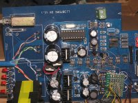
Thanks for the prod - as a result I've at last gotten around to the promised photoshoot and here's the first pic. I'll draw up some schematics by hand based on the pics, just to be certain y'all get diagrams based on what does actually work in practice
The discrete I/V stages can be seen just underneath the row of DAC chips. The I/V resistors I have are 1.1k (marked 112) and they're soldered directly to the collectors of the I/V transistors (BC807s) - the other side of those resistors is analog ground. The BC807 emitters go to the DAC outputs and the bases go, via ferrite beads, to a reference voltage generated by a TL431 shunt. That's in a TO92 package on the north side of the DACs and its decoupled by the 'lytic to its right (220uF). I think that I chose the reference to output around 4.5V but I'll need to check the resistor values to be sure. Incidentally the positive side of the 220uF cap isn't going to any PCB traces, its just floating above the solder mask.
<edit> On reflection I now consider those 1.1ks as overly optimistic values - probably I'm running into saturation of the I/V transistors on digital peaks, so I'll scale them back a little. Ah no - scratch that - I remember now that the filter impedance being fed from them is also around the same value so the AC impedance seen is about half that of the 1k1, no issue. Duh!
Attachments
Last edited:
Abraxalito: thank you again for the endless stream of useful info you keep adding to this thread!
On a slightly different note: regarding the opamp constant current source mod, is that circuit specific to the AD845?
I ask because I'm flirting with the idea of playing the opamp rolling game. I should also update the wiki if that CCS circuit is AD845 specific.
(Also, I figure opamp rolling is something easy and fun to do while I prepare for the next gen mod, which will probably take me a while.)
Thanks again!
You're welcome - thanks for the continued interest!
The CCS mod is almost entirely a generic one. I say 'almost' because there are probably opamps out there which won't be able to supply the additional output current but I can't think of one off hand. So pretty much any opamp will do which can supply 10mA from its output stage.
The CCS mod is almost entirely a generic one. I say 'almost' because there are probably opamps out there which won't be able to supply the additional output current but I can't think of one off hand. So pretty much any opamp will do which can supply 10mA from its output stage.

OpAmps are that much involved in overall sound?
Hi Matt, don't know if it's funny, sadly I find it top be necessary. I have my CD player wich is, in my home, my reference (in the meaning it's what I can comapre things againts). I must say that my studio monitors speakers have no mercy and show all flaws.
And the opamp rolling is in my case what will determine wich gear to keep, wich to trash. If I use AD845, OPA602, AD844 and friends I do not keep the DAC (used with VRDS 10 as source), as it's less good than my CD player. AD844 wich is my waiting opamp, has less bass and too much mids/high-mids.
If I keep a stable LT1028-like-sound I keep the DAC as it betters my CD player everywhere. Needless to say that other opamps are nowhere near.
As you see it's very important and I would never have guessed that a single IC will make me use this DAC or scrap it. Or prior to recycling bin I'll try the so much praised for Richard's full output circuit?
Share your findings guys!
(...) I'm flirting with the idea of playing the opamp rolling game. (...)
(Also, I figure opamp rolling is something easy and fun to do while I prepare for the next gen mod, which will probably take me a while.)
Hi Matt, don't know if it's funny, sadly I find it top be necessary. I have my CD player wich is, in my home, my reference (in the meaning it's what I can comapre things againts). I must say that my studio monitors speakers have no mercy and show all flaws.
And the opamp rolling is in my case what will determine wich gear to keep, wich to trash. If I use AD845, OPA602, AD844 and friends I do not keep the DAC (used with VRDS 10 as source), as it's less good than my CD player. AD844 wich is my waiting opamp, has less bass and too much mids/high-mids.
If I keep a stable LT1028-like-sound I keep the DAC as it betters my CD player everywhere. Needless to say that other opamps are nowhere near.
As you see it's very important and I would never have guessed that a single IC will make me use this DAC or scrap it. Or prior to recycling bin I'll try the so much praised for Richard's full output circuit?
Wonder what that will do as the LT1128 is "only" 6V/µs... not the same as LT1028... I pray every evening all the Gods and burn a candle, hope LT1128 will be sounding exactly las LT1028 but being stable... (some readings found the LT1128 not table either and sounding not as good... and some just as great as LT1028 and stable...).Audio signals are around 20khz max freq and 8V/us
Share your findings guys!
Wonder what that will do as the LT1128 is "only" 6V/µs... not the same as LT1028... I pray every evening all the Gods and burn a candle, hope LT1128 will be sounding exactly las LT1028 but being stable... (some readings found the LT1128 not table either and sounding not as good... and some just as great as LT1028 and stable...).
Share your findings guys!
The SR about 6V/us set the limit at maximum Vout peak to peak you can find best value by a simple calculus . SR is not the main variable on the good sounding ,
the THD composition is the main variable so difficult to evaluate before made the circuit ....

My experience recently is quite far from that. I wanted to test a hypothesis that its PSRR, not THD which is the primarily determinant of how an amp sounds. PSRR is one thing that's fairly easy to evaluate in simulation, so I designed my amp to give the best possible PSRR in simulation, then built it. Very happy indeed with the sound as built, no tweaks were necessary in practice - its only a headphone amp though. Next step is to scale it up to speaker level.
Discrete IV stage
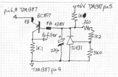
At long last here's the schematic (hand drawn as LTSpice's TL431 symbol is really confusing) for the discrete I/V modification.
Implementing the balanced outputs requires four of the BC807s (or BC327s if you're doing this non-SMT) plus associated FBs and 1k1 resistors. Only one TL431, 220uF and set of voltage setting resistors is required though - there's plenty of current available to feed the 3.8V voltage reference to 4 I/V transistors.
<edit> Incidentally I've implemented a couple more lily-gilding mods to my current DAC. First I've replaced the resistors feeding the shunts from the res caps with LM317s configured as CCSs in series with resistors for ballast. This gave a subtle improvement in bass 'weight' or definition probably as a result of having better LF PSRR with the current source. These 317s have been included on all three of the analog supplies (but not the digital). I'm also experimenting with adding biassing current sources to the I/V transistors which I'll talk about if there's any interest in that.
Attachments
Last edited:
At long last here's the schematic (hand drawn as LTSpice's TL431 symbol is really confusing) for the discrete I/V modification.
Implementing the balanced outputs requires four of the BC807s (or BC327s if you're doing this non-SMT) plus associated FBs and 1k1 resistors. Only one TL431, 220uF and set of voltage setting resistors is required though - there's plenty of current available to feed the 3.8V voltage reference to 4 I/V transistors.
Thank you for that! I'll go back and review everything that's been discussed... I may have more questions.
But for now I'll study all the info you've provided.<edit> Incidentally I've implemented a couple more lily-gilding mods to my current DAC. First I've replaced the resistors feeding the shunts from the res caps with LM317s configured as CCSs in series with resistors for ballast. This gave a subtle improvement in bass 'weight' or definition probably as a result of having better LF PSRR with the current source. These 317s have been included on all three of the analog supplies (but not the digital). I'm also experimenting with adding biassing current sources to the I/V transistors which I'll talk about if there's any interest in that.
I'm interested, though asking for more detail now is getting ahead of myself.
I just noticed they have an emoticon for the pace at which I work:

Thanks again!
- Home
- Source & Line
- Digital Line Level
- TDA1387 x8 DAC: let's check its design, mod it -or not-, play music -or not! :(-