I'm a third year electrical engineering student and audio enthusiast who just stared designing electronics. This project is an opportunity for me to learn DAC design, sourcing components and manufacturing a PCB. My goal is to build a cheap mini USB DAC that is an improvement on an integrated PC sound card. The biggest inspirations for this project were the Stoner UD100 sound card and 00940’s project on this forum.
My design constraints were the following:
- The PCB must slide into a 40x25x25mm metal case.
- Parts must be available for consumers in the Netherlands, preferably at TME.
- All parts need to be in the smallest package available without compromising on quality, preferably 0603.
- The design must incorporate the best possible ESD/EMI protection that fits the board.
- Device must be connected via 3.5mm jack and micro USB sockets.
- The PCB will be 2 layer at OSH Park.
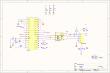
When designing a minimalistic DAC it’s hard not to use the TI PCM5102A. Not only had this DAC great sound quality specification for the price but it also has built in charge pumps which give 2V RMS at the output. This allows for an output stage without op amps or many passives. It also has a soft mute input reduce popping sounds when power is disconnected.
For USB to I2S I’ve decided to use the TI PCM2707. This is one of the only USB input receivers that is available in small quantities. It’s limited at 16Bit/48kHz but well documented and very simple to use.
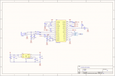
The PCM2707 is set up in bus powered mode and the PCM5102 has its own TI TPS73033 LDO for 3.3V. Both IC’s power lines pass through ferrite beads for noise suppression.
For USB data line termination and ESD/EMI protection I’ve looked at multiple setups. The best option would be resistors, TVS diodes and a common mode choke. This method would take up way too much space on the board. The usable alternative would be a ST USBUF02W6 USB termination IC. This 6 pin SOT323 package contains all needed resistors, TVS diodes and capacitors for USB data lines and uses very little PCB space.
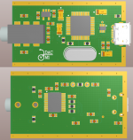
The PCB should slide in this 40x25x25mm metal case. Not only is this case very cheap but it also looks nice. Because the case is made out of metal some ESD precautions should be taken. In this design I’ve put bare metal slots at the sides of the PCB connected to case ground.
To dissipate ESD strikes the case ground should be connected to system ground through a filter. It seems that every manufacturer has a different approach to this issue. I’ve used the most common approach of a 1M resistor and a 4.7nF cap connected between grounds.
At the moment I still have a few hesitations:
- The PCB slot in the case is 23.3mm wide with a tolerance of 0.15mm. The PCB manufacturer also has a tolerance for the board cutout. The gap between the PCB and case should be as small as possible without getting stuck. How wide should the PCB be?
- The USB input has a ferrite bead at the power line and case ground connections mentioned above. Since there are many options per manufacturer I would like to know if my solution is the right one.
- For the power supply I’ve used tantalums for polarized caps. Should I use low ESR versions on the board or regular ones?
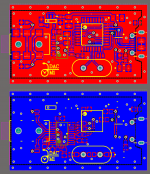
- Because of the small size of the PCB (40mmx23mm) It wasn’t possible to use separate analog and digital ground planes. In this design the top and bottom planes are connected by many vias to ensure the best return paths. Are there improvements to this approach?
I’ve included the schematics, PCB layout and 3D view below. Critique and suggestions are appreciated.
My design constraints were the following:
- The PCB must slide into a 40x25x25mm metal case.
- Parts must be available for consumers in the Netherlands, preferably at TME.
- All parts need to be in the smallest package available without compromising on quality, preferably 0603.
- The design must incorporate the best possible ESD/EMI protection that fits the board.
- Device must be connected via 3.5mm jack and micro USB sockets.
- The PCB will be 2 layer at OSH Park.
When designing a minimalistic DAC it’s hard not to use the TI PCM5102A. Not only had this DAC great sound quality specification for the price but it also has built in charge pumps which give 2V RMS at the output. This allows for an output stage without op amps or many passives. It also has a soft mute input reduce popping sounds when power is disconnected.
For USB to I2S I’ve decided to use the TI PCM2707. This is one of the only USB input receivers that is available in small quantities. It’s limited at 16Bit/48kHz but well documented and very simple to use.
The PCM2707 is set up in bus powered mode and the PCM5102 has its own TI TPS73033 LDO for 3.3V. Both IC’s power lines pass through ferrite beads for noise suppression.
For USB data line termination and ESD/EMI protection I’ve looked at multiple setups. The best option would be resistors, TVS diodes and a common mode choke. This method would take up way too much space on the board. The usable alternative would be a ST USBUF02W6 USB termination IC. This 6 pin SOT323 package contains all needed resistors, TVS diodes and capacitors for USB data lines and uses very little PCB space.
The PCB should slide in this 40x25x25mm metal case. Not only is this case very cheap but it also looks nice. Because the case is made out of metal some ESD precautions should be taken. In this design I’ve put bare metal slots at the sides of the PCB connected to case ground.
To dissipate ESD strikes the case ground should be connected to system ground through a filter. It seems that every manufacturer has a different approach to this issue. I’ve used the most common approach of a 1M resistor and a 4.7nF cap connected between grounds.
At the moment I still have a few hesitations:
- The PCB slot in the case is 23.3mm wide with a tolerance of 0.15mm. The PCB manufacturer also has a tolerance for the board cutout. The gap between the PCB and case should be as small as possible without getting stuck. How wide should the PCB be?
- The USB input has a ferrite bead at the power line and case ground connections mentioned above. Since there are many options per manufacturer I would like to know if my solution is the right one.
- For the power supply I’ve used tantalums for polarized caps. Should I use low ESR versions on the board or regular ones?
- Because of the small size of the PCB (40mmx23mm) It wasn’t possible to use separate analog and digital ground planes. In this design the top and bottom planes are connected by many vias to ensure the best return paths. Are there improvements to this approach?
I’ve included the schematics, PCB layout and 3D view below. Critique and suggestions are appreciated.
Last edited:
Hey i am an EE student of year 3 too, and i am also going to work on a similar project as well.
For the linear regulator, I think there are some better options, like TI, TPS7A4700 and ADM7150 which has lower noise.
Is you application is driving a headphone or earphone, I m not sure if the output of pcm5102 is powerful enough.
For the linear regulator, I think there are some better options, like TI, TPS7A4700 and ADM7150 which has lower noise.
Is you application is driving a headphone or earphone, I m not sure if the output of pcm5102 is powerful enough.
- Status
- This old topic is closed. If you want to reopen this topic, contact a moderator using the "Report Post" button.