Hello,
I have two WM8741 DACs (in mono mode) in my player. I am planning to design a passive transformer output stage for these DACs.
The differential outputs of the DACs are biased at 2.5V. Possible transformer wiring options that come to my mind are the following:
Option 1:
Option 2:
Option 3:
Option 4:
I have a few questions regarding this approach. Any feedback would be greatly appreciated.
Can you please recommend an option? Are the other options?
What would be a suitable transformer?
Do I need resistors in series with the coils?
Should I add high or low pass filters?
Thanks a lot!
Wutzke
I have two WM8741 DACs (in mono mode) in my player. I am planning to design a passive transformer output stage for these DACs.
The differential outputs of the DACs are biased at 2.5V. Possible transformer wiring options that come to my mind are the following:
Option 1:
An externally hosted image should be here but it was not working when we last tested it.
Option 2:
An externally hosted image should be here but it was not working when we last tested it.
Option 3:
An externally hosted image should be here but it was not working when we last tested it.
Option 4:
An externally hosted image should be here but it was not working when we last tested it.
I have a few questions regarding this approach. Any feedback would be greatly appreciated.
Can you please recommend an option? Are the other options?
What would be a suitable transformer?
Do I need resistors in series with the coils?
Should I add high or low pass filters?
Thanks a lot!
Wutzke
An externally hosted image should be here but it was not working when we last tested it.
This is a pair of suitable and very good transformers: http://www.diyaudio.com/forums/swap-meet/266109-jensen-jt-11-ympc-dac-output-transformers-pair.html
I used some LL1690 as you did in Option 2, but my in-line resitors are 1k and the tranformer's ground pin tied to OUT - and no resistor across Out + and Out -.
I used some LL1690 as you did in Option 2, but my in-line resitors are 1k and the tranformer's ground pin tied to OUT - and no resistor across Out + and Out -.
I used the Jensen JT-11-DMPC with amazing results. Series resistors are not needed and discouraged. The specifications in the data sheet apply to AC impedance, of which the transformer is huge. As long as you keep your connected load impedance within spec you will have no issues. There is no DC coming out of the differential DAC, so you don't need to meet a DC resistance minimum load spec.
Your connection options really depend on the gain structure of your system, not so much which one would sound better than the other. For a decent transformer they will (barring that third diagram) be the same but with potentially different output voltages.
Regarding transformers try and make sure you are purchasing an output transformer, not an input transformer or something else not specifically designed for output service. Jensen's website has some nice articles on the differences between input and output transformers.
@Groundloops, is your primary center tap connected to GND?I used some LL1690 as you did in Option 2, ...
@zigzagflux, did you used the JT-11-DMPC with a WM8741 DAC? If yes, could you please shortly describe your wiring.I used the Jensen JT-11-DMPC with amazing results. ...
No, I use the AK4393, which is very similar to the WM8741. They are both 24 bit Delta Sigma and use differential voltage outputs. The WM8741 has a higher maximum sampling rate.
Wiring is easy as can be- tie the two DAC voltage output pins to pins 2 and 5 of the Jensen. Pins 8 and 11 are the transformer output, which you can use either balanced or unbalanced.
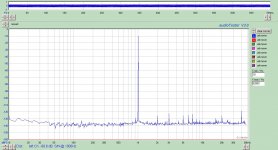
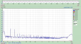
Distortion is nearly identical to that published by AKM, indicating the transformer added almost nothing to the signal. I am sure my sound card setup was not perfect, either. The 20Hz FFT in particular I am pleased with. Not easy to do with a transformer.
Wiring is easy as can be- tie the two DAC voltage output pins to pins 2 and 5 of the Jensen. Pins 8 and 11 are the transformer output, which you can use either balanced or unbalanced.
Distortion is nearly identical to that published by AKM, indicating the transformer added almost nothing to the signal. I am sure my sound card setup was not perfect, either. The 20Hz FFT in particular I am pleased with. Not easy to do with a transformer.
Attachments
dont connect CT tap of primary at the Ground potential. You vill have DC from 2.5V to 0v across Rdc of windings. SAnd may damage the dac chip.
Connect to Vmid pin (there is the same potential as one at the analog outputs...
.
I am not sure that chip has driving capabilities to meet the transformer reactive impedance values. So it is not bad idea to use some low impedance output buffer.
cheers")
Connect to Vmid pin (there is the same potential as one at the analog outputs...
.
I am not sure that chip has driving capabilities to meet the transformer reactive impedance values. So it is not bad idea to use some low impedance output buffer.
cheers
@Groundloops, is your primary center tap connected to GND?
No. Zoran gives the explanation why. It's a frequent misconception to connect the center tap to the DAC's GND.
Seems like a good option. Since ALL DAC outputs are at 2.5V there is no DC current through the coils. No need to put anything on the center taps - in fact grounding the center tap would be a recipe for disaster. Putting 2.5V at the center tap is pretty useless - it would do nothing good but requires a 2.5V source exactly the same as the DAC DC output, and also for some pretty critical decoupling.
Option 1 is the most sensible.
Jan
Option 1 is the most sensible.
Jan
@zigzagflux, @Groundloops, is your output stage passive? Or do you have an output buffer?I am not sure that chip has driving capabilities ...
the dac is not the driver it is just generator. dac chip have no capabilities for driving complex loads. Simply internal resistance of the generator or output impedance, is too high. As the that value is higher, the driving power is decreasing.
So if You have that week source, it deserves a higher value of primary inductance at interstage transformer. So this arrangement with serial 2+2 for each pos and neg rail will increase the inductance with result in better lower Fo and wider low bw, with smaller phase shift...
BUT
with increasing primary inductance nuber of turns is higher a lot. So that increase capacitances and not this on the primary layers, but and the secondary too because of the transfer ratio, it will passing to each side mutually... That will cause loss in top end, ringing of the transformer, disturbing phase and etc...
.
So conclusion is that trasformer likes lower impedances at the source. Much lower than voltage dac chips are. basically it is not the design goal for dac chip to drive anything
especially the interstage transformer or any other highly reactive load
That is my opp.
The WM8741 delivers 2,00V into 10 kOhm in PCM mode. I've set it up with in dual mono mode with a pair of Lundahl LL1690 transformers as said earlier in this thread, going directly into a 10 kOhm potentiometer and from there into my SymAsym Amps. Works like a charm ...
Attachments
@All, what do think about option 1?
The DAC has two differential outputs, the LL1527 (for example) has two primary coils. I could connect OUT1+/OUT1- to the first coil and OUT2+/OUT2- to the second coil.
Hi,
I have asked same in this thread:
http://www.diyaudio.com/forums/digital-line-level/261711-0-5-0-5-1-line-transformer-question.html
This is my current setup of my dual AK4399 mono dac kit using similar dual primary transformer (Haufe RK736). I didn't try other options since I'm quite happy with the sound.
Btw, I need an advice for protecting my dac outputs for a possible overload. People tend to use some resistors in series at dac outputs but I have no idea about drawbacks of this.
Regards.
Last edited:
I forgot to mention that you must strictly take care of in-phase connection of primary windings of option 1. If you put the primary windings out of phase, it acts as short-cut thus overload and possibly damaged chip. I suggest you to finger tip chips for monitoring a possible sudden rise of heat while powering up.
A question:
WM8471 has 2.5V analog mid rail voltage (VMIDR VMIDL).
If ground pin of balance out is connected to VMIDR/VMIDL, the output transformer would be needed?
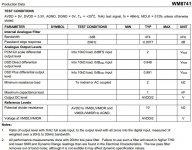
With 2V swing and 600ohm impedance (with dual mono configuration with 5V psu), it seems WM8471 can drive 10K+ load power amps directly.
WM8471 has 2.5V analog mid rail voltage (VMIDR VMIDL).
If ground pin of balance out is connected to VMIDR/VMIDL, the output transformer would be needed?
With 2V swing and 600ohm impedance (with dual mono configuration with 5V psu), it seems WM8471 can drive 10K+ load power amps directly.
Last edited:
I agree that #1 seems the most sensible. I've used transformer outputs on at least 4 different brands of voltage out DAC chips with no problems.
Don't give them too light a load, and you may need a snubber cap if the transfo rings. Not usually a problem tho.
Off the shelf Jensen are nice, but I also like my Cinemag and Onetics. Even Edcor are OK. It's easy to get good results. Go for it. .
Don't give them too light a load, and you may need a snubber cap if the transfo rings. Not usually a problem tho.
Off the shelf Jensen are nice, but I also like my Cinemag and Onetics. Even Edcor are OK. It's easy to get good results. Go for it. .
I am completely confused after reading this tread.
When I was building my LL1527XL based output, I had in mind the following line from the datasheet:
Minimal resistance load - to midrail or AC coupled - 2 kohm
At that time I have found a schematic that had primaries connected in series and 10kohm || 2.2 uF connected to the center tap, as well as 10k across secondaries also in series. This made sense to me as I thought it would give required minimum resistance to the midrail (in fact maybe too much), and in terms of DC current it induced about 2.5mA to each primary but the resulting flux would cancel each other, hence no saturation of the core. In practice everything works nice, the sound is far better than with previous output filter based on an operational amplifier.
But after reading this post I am thinking more about the AC coupled resistance. If the center tap on the primary would float, what would be AC coupled resistance, given that the DAC and output don't have a common ground?
Cheers,
Boris
- Status
- This old topic is closed. If you want to reopen this topic, contact a moderator using the "Report Post" button.
- Home
- Source & Line
- Digital Line Level
- WM8741 dual differential, passive, transformer output stage