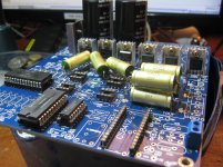
Going to dump some photos here for the time being this is just a rough slap together of what components the final product might be using.
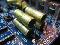
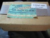
Extensive use of 0.022uF k73-15's and soon-to-arrive 22uF K73-16's.
Main rectifier Diodes will be Russian D7J's Germaniums from Russia. (If they don't blow up with this much capacitance.)
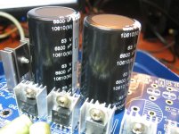
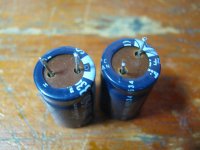
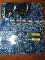
Two of the PSU caps are 6800uF 63v Panasonic TSU Series that I have had for some time now. I like lots and lots of Capacitance, I'm using the experience I've had with the previous TDA1543 DAC and the amount of capacitance there was 22,000uF. I also like the idea of using a higher voltage one than is necessary to reduce any potential micro-phonics in the front line of power supply filtering.
Main Transformer is an R-Core with the following windings:
1x 18v-0v-18v
3x 9v
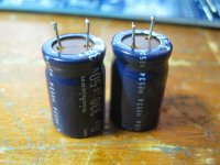
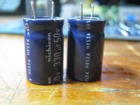
Post-Regulator caps will/are going to be Elna Cerafine 100uF-470uF (Might also use 22uF K73 in an Adjustment capacitor arrangement, reasons: http://www.tnt-audio.com/clinica/regulators_noise2_e.html )
& Post-post Regulator caps (for RF/Noise filtering) will again be the low-value K73's
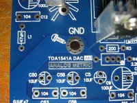
TDA1541 & SAA7220P/A are both 100% Genuine CDP pulls. (I want to see what the PCB sounds like when fully populated and then depopulate it according to my tastes, yes this means also fitting OPAMPS, you never know I might like the sound of them more than straight old Passive I/V conversion.)
TDA1541 Coupling caps are again, you guessed it, K73's though I might swap these out fairly often with different values and try other brands aswell.
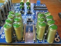
TDA1541 Decoupling caps will be 0.470uF K73-16's if I can find some if I can't however I may get some thats slightly smaller in value. What is in there at the moment for first-test run purposes is 2x 0.022uF in parallel which makes 0.044uF. I've had great results with these in the TDA1543 DAC project I made a while ago.
Feed from a rear BNC to the board SPDIF will be RG-316 Coax.
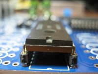
Receiver chip is CS8412-CP.
I must say that this PCB is truly high quality with very very nice through-holes, but this does make it a mongrel to desolder if you need to.
Thats all I can share and be certian of for now. Welcome any suggestions.
Extensive use of 0.022uF k73-15's and soon-to-arrive 22uF K73-16's.
Main rectifier Diodes will be Russian D7J's Germaniums from Russia. (If they don't blow up with this much capacitance.)
Two of the PSU caps are 6800uF 63v Panasonic TSU Series that I have had for some time now. I like lots and lots of Capacitance, I'm using the experience I've had with the previous TDA1543 DAC and the amount of capacitance there was 22,000uF. I also like the idea of using a higher voltage one than is necessary to reduce any potential micro-phonics in the front line of power supply filtering.
Main Transformer is an R-Core with the following windings:
1x 18v-0v-18v
3x 9v
Post-Regulator caps will/are going to be Elna Cerafine 100uF-470uF (Might also use 22uF K73 in an Adjustment capacitor arrangement, reasons: http://www.tnt-audio.com/clinica/regulators_noise2_e.html )
& Post-post Regulator caps (for RF/Noise filtering) will again be the low-value K73's
TDA1541 & SAA7220P/A are both 100% Genuine CDP pulls. (I want to see what the PCB sounds like when fully populated and then depopulate it according to my tastes, yes this means also fitting OPAMPS, you never know I might like the sound of them more than straight old Passive I/V conversion.)
TDA1541 Coupling caps are again, you guessed it, K73's though I might swap these out fairly often with different values and try other brands aswell.
TDA1541 Decoupling caps will be 0.470uF K73-16's if I can find some if I can't however I may get some thats slightly smaller in value. What is in there at the moment for first-test run purposes is 2x 0.022uF in parallel which makes 0.044uF. I've had great results with these in the TDA1543 DAC project I made a while ago.
Feed from a rear BNC to the board SPDIF will be RG-316 Coax.
Receiver chip is CS8412-CP.
I must say that this PCB is truly high quality with very very nice through-holes, but this does make it a mongrel to desolder if you need to.
Thats all I can share and be certian of for now. Welcome any suggestions.
Attachments

Last edited:
What advantage do you expect from the Germanium diodes?
Unfortunately I do not know Russian, but looking at the datasheet, I think the diodes won't stand a chance with that kind of filter-capacitance...
@22.000uF the diodes ought to withstand a lot of "peak Amperes".
NB.: Keep in mind that the SAA7220 is a notorious source of noise on the power-supply line. Decoupling with only a resistor and a capacitor will not do (for best performance).
Last edited:
What advantage do you expect from the Germanium diodes?
Lower switching noise.
I see you're from the Netherlands. Nice. I used to have a friend who used to live there, nice internet speeds? He lives in Sweden now.
I reckon they would stand a chance, they're tough Ombre's, they're here to party and drink Vodka. I say I give them a shot at it.Unfortunately I do not know Russian, but looking at the datasheet, I think the diodes won't stand a chance with that kind of filter-capacitance...
I won't be using 22,000uF, the most that four of them will see is 6800uF or lower. if they blow at 6800uF I'll lower it.
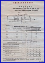
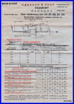
Here is a translation that I've made tonight
Attachments

Last edited:
I'm afraid the noise generated by the SAA7220 is a multiple on the regulated PS-line. Is PS-regulation done by LM's or so? These device are very good at suppressing noise and so within the audio frequencies and a bit above, but not so good in the 1Mhz+ range (saa7220)... There you have to suppress noise using passive measures.Lower switching noise.
yes & yes.. Sweden seems to be a nice country too...I see you're from the Netherlands. Nice. I used to have a friend who used to live there, nice internet speeds? He lives in Sweden now.
OK, let's hope for the best... And thanks for the translation..I reckon they would stand a chance, they're tough Ombre's, they're here to party and drink Vodka. I say I give them a shot at it.
I won't be using 22,000uF, the most that four of them will see is 6800uF or lower. if they blow at 6800uF I'll lower it.
Here is a translation that I've made tonight

I'm afraid the noise generated by the SAA7220 is a multiple on the regulated PS-line. Is PS-regulation done by LM's or so? These device are very good at suppressing noise and so within the audio frequencies and a bit above, but not so good in the 1Mhz+ range (saa7220)... There you have to suppress noise using passive measures.
Its... how should I put it... a visitor anyway.
I'm going to see what it sounds like and then remove it and the 74HC4040 from the circuit and put it back in and then remove it again. To make 100% Sure that I like it out of the circuit.
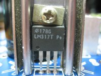
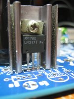
Yes I'm going to acquire 100% genuine LM317/LM337's over the next few years, only one LM317 which is on the Analog PSU circuit at the moment is 100% Genuine that I can vouch for, I'll add a picture of it to the end of this message.
The one in the pictures below isn't from eBay, I got it from a parts bin that was over 30 years old and was owned by my uncle who passed away.
I'll paste 'some' pictures of my TDA1541 NON-A in the next post.
No problems, hopefully it can be of some use to someone else who uses the germanium diodes.OK, let's hope for the best... And thanks for the translation..
I'm thinking that to get around the inrush current being a problem that we could use a soft start circuit. (IF it becomes a problem)
Attachments
Last edited:
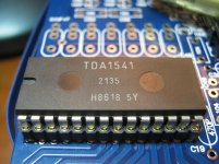
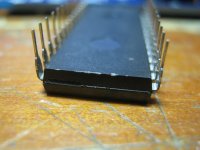
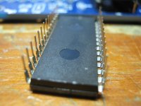
Here are the pics of my TDA1541 NON-A
To add to its authenticity:
It came from a Marantz CD-65 Mark 1 which was made in 1986.
When I pulled it it was covered in dust.
The pits are nice and smooth and the surface looks non-sanded & non-painted.
The date code on the 1541 is H8618.
The power supply capacitors were made in ... H8534...
The SAA7220P/A has a date code of DGG8601M2Y
It sounds FANTASTIC!
Attachments
-
 Picture 008s.jpg295.2 KB · Views: 95
 -
 Picture 007s.jpg306.9 KB · Views: 98
 -
 Picture 006s.jpg425 KB · Views: 145
 -
 Picture 005s.jpg365.5 KB · Views: 125
 -
 Picture 004s.jpg327.7 KB · Views: 154
 -
 Picture 003s.jpg277.6 KB · Views: 163
 -
 Picture 075s.jpg376.8 KB · Views: 126
 -
 Picture 078s.jpg286.4 KB · Views: 114
 -
 Picture 077s.jpg285.9 KB · Views: 118
 -
 Picture 076s.jpg289 KB · Views: 173
Last edited:
Looks good too..Here are the pics of my TDA1541 NON-A
To add to its authenticity:
It came from a Marantz CD-65 Mark 1 which was made in 1986.
When I pulled it it was covered in dust.
The pits are nice and smooth and the surface looks non-sanded & non-painted.
The date code on the 1541 is H8618.
The power supply capacitors were made in ... H8534...
The SAA7220P/A has a date code of DGG8601M2Y
It sounds FANTASTIC!
The non-A is not necessarily less than an A... so no problem there

Give it some time to burn-in and then set up a good listening session.
There is one tiny difference between the A and the non-A : the non-A has an internal capacitor for the DEM-frequency, the A external (C19: 470p).
Last edited:
Looks good too..
The non-A is not necessarily less than an A... so no problem there
My thoughts exactly if anything the N-A is better from what I've read on here and other sites. (Has more "punch")
Its certianly more common and less expensive!
This kit isn't completed just yet, I was reminiscing of the time when I did have it working in the Marantz CD-65 and was playing CD's.Give it some time to burn-in and then set up a good listening session.
Thanks for that information, the knowledge of its internals is few and far between on the web.There is one tiny difference between the A and the non-A : the non-A has an internal capacitor for the DEM-frequency, the A external (C19: 470p).
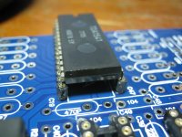
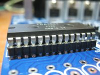
Errr...
Ummm....
Is that a ... a
... RainDropHui DAC?
...
Probably, maybe a cousin of a cousin copied it off a cousin.
The logo says Analog Metric though so I go with whatever it says.
Its certianly a very thick PCB (3mm), and a gorgeous board. The layout of the traces are arguable though.
Attachments
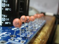
I'm gonna need some more 104 Ceramics I think..... Just dried up the last of my supply!
Maybe I'll get some higher voltage 104's. That would probably worsen Microphonics though. I should be able to get some PETP caps in this value so I might use them instead.
Still have plenty of PETP 0.022uF caps.
Project postponed until additional components arrive (2-4 weeks)
Maybe I'll get some higher voltage 104's. That would probably worsen Microphonics though. I should be able to get some PETP caps in this value so I might use them instead.
Still have plenty of PETP 0.022uF caps.
Project postponed until additional components arrive (2-4 weeks)
Attachments
Last edited:
Shopping for some Class 1 Ceramic capacitors. (To avoid microphonics, class 2 has microphonic issues.)
https://en.wikipedia.org/wiki/Ceramic_capacitor#Microphony
EDIT: Scored some Ex-Military Glass-Sealed Axial Ceramics (usually used in ultra-reliable military circuits) 0.1uF 50v
eBay item number:
141025647501
https://en.wikipedia.org/wiki/Ceramic_capacitor#Microphony
EDIT: Scored some Ex-Military Glass-Sealed Axial Ceramics (usually used in ultra-reliable military circuits) 0.1uF 50v
eBay item number:
141025647501
Attachments
Last edited:
Hi Freax,
have you please a link for the R-core traffo... ?
i hesitate also for the same output cap as yours as I have only two BG N for my TDA 1541 projects (One Distinction-1541 & two recent AYA 2 2014... you should go for it if Audial goes again whith such special low cost DIY operation). A good link for those caps ?
Could be also interresting you benchmark the big DEM caps with little Wima MKS2 but in 2.5 mm legs pitch. Inductance is important also... A proof of concept will tell you, it's good to test it with ears.
I will testimonie about A & Non-A as soon as my first project will be finish also !
cheers Freax
have you please a link for the R-core traffo... ?
i hesitate also for the same output cap as yours as I have only two BG N for my TDA 1541 projects (One Distinction-1541 & two recent AYA 2 2014... you should go for it if Audial goes again whith such special low cost DIY operation). A good link for those caps ?
Could be also interresting you benchmark the big DEM caps with little Wima MKS2 but in 2.5 mm legs pitch. Inductance is important also... A proof of concept will tell you, it's good to test it with ears
.I will testimonie about A & Non-A as soon as my first project will be finish also !
cheers Freax
Last edited:
Hi Freax,
have you please a link for the R-core traffo... ?
eBay item number:
221113013675
Enter this into the search box of eBay.
Do a search on eBay for k73-15 or k73-16 or k73i hesitate also for the same output cap as yours as I have only two BG N for my TDA 1541 projects (One Distinction-1541 & two recent AYA 2 2014... you should go for it if Audial goes again whith such special low cost DIY operation). A good link for those caps ?
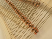
Yes I have quite a few coils ready to be put into the circuit for ear-testing. I scavenge these ready-made from old blown ATX PSU's. But they are of a random mH value and I don't have a meter to check them.Could be also interresting you benchmark the big DEM caps with little Wima MKS2 but in 2.5 mm legs pitch. Inductance is important also... A proof of concept will tell you, it's good to test it with ears
I will testimonie about A & Non-A as soon as my first project will be finish also !
cheers Freax
eBay item number:
261546496952
These are nice however so might just buy them. The question is however what value to choose? I will need to learn some more about filtering the noise output of the LM317/337's.
I've got the premise of building this circuit around the notion that any RF present on the DC traces will invariably cause jitter.
So i've gotta isolate and compartmentalize... Which means more chokes and ferrite based chokes.
Something like this perhaps:
eBay item number:
351190288209
Schematic: http://www.analogmetric.com/gallery.php?id=102
The main inductance value on the board/circuit is 47uH in the lm317 power supply circuit, I may use a higher value the through-holes on the pcb are large enough to support maybe 1-2mm of copper wire.
Not sure if I will be using WIMA MKS2 caps, they are $5 each! Would be cheaper to simply buy the russian PETP equivalent. Getting them in the board however is a different matter.
Will be doing more research and taking this one step at a time.
Last edited:
The fact that the voltage regulator is far away from the TDA1541 is kind of a good thing, not sure why people think having a voltage regulator right on the chip is a good thing when you've gotta remove the noise of the LM317/337's... Especially when you put a choke into the circuit it radiates some of the RF hash into the air surrounding it.
http://www.digikey.com/Web%20Export/Supplier%20Content/Laird_776/PDF/laird-sip-an-common-mode-choke-filtering.pdf?redirected=1
From my gathering of that it appears that a common mode choke would be ideal. From my gathering of the PCB this will be difficult without cutting the ground traces. maybe an alternative method of implementing current mode filtering would be possible without cutting the ground traces.
Last edited:
The 47uF chokes as shown in the schematic are simply differential mode chokes which serve nothing but to isolate each circuit from each other. Which is good in its own right but serves only to prevent ground loops essentially.
But for great results there must also be common mode chokes put in place, possibly on the bottom side of the PCB.
http://www.mag-inc.com/File%20Library/Product%20Literature/Ferrite%20Literature/fc-s5.pdf
http://www.murata.com/en-global/products/emiconfun/emc/2011/10/28/en-20111028-p1
But for great results there must also be common mode chokes put in place, possibly on the bottom side of the PCB.
http://www.mag-inc.com/File%20Library/Product%20Literature/Ferrite%20Literature/fc-s5.pdf
http://www.murata.com/en-global/products/emiconfun/emc/2011/10/28/en-20111028-p1
With the R-Core transformer I figured I could wind two of the three available 9vAC windings in series to make a 18v winding suitable to feed for the 15v input on the PCB.
So the transformer comes wired as such:
1x 18v-0v-18v (Center Tapped)
3x 9v-0v (No CT)
And I'm wiring it as such:
1x 18v-0v-18v (For the 20vAC PCB input)
1x 9v-0v-9v (ignoring the CT makes it a 18v-0v winding, no CT) (For the 15vAC PCB input) (Ignore the CT that is created as a result of joining these two windings together, Solder them together and then tape it up with heatshrink, you won't need it.)
1x 9v-0v (Don't use)
I will need a second transformer for the 12vAC/5v Regulated bus. The 9vAC 0.3A winding is after thinking about it too small to feed four individal buses.
Last edited:
- Status
- This old topic is closed. If you want to reopen this topic, contact a moderator using the "Report Post" button.
- Home
- Source & Line
- Digital Line Level
- My version of the TDA1541 Analog Metric DAC