")


Really impressive! Does this board allow F.I.R. filtering?
I don't think it's a matter of the board, it's probably more of a question about ADAU170 at Engineer Zone:
FIR and general filtering on ADAU1701. Hints ab... | EngineerZone
Last edited:
I don't think it's a matter of the board, it's probably more of a question about ADAU170 at Engineer Zone:
FIR and general filtering on ADAU1701. Hints ab... | EngineerZone
Thanks for the link. The journey begins I think.
I'm looking for something that I can use that has both quality and versatility.
The idea of working with passive loudspeaker filters is pretty much a non starter over here. All my design work in the past six years has been active only.

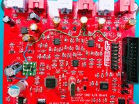
Nice board
Is the board called AWDSP?
Can it be considered as a "next generation" freeDSP?
Can we buy a board - either fully populated, or just the SMDs done, or ..?
10cmX10cm.
Is the board called AWDSP?
Can it be considered as a "next generation" freeDSP?
Can we buy a board - either fully populated, or just the SMDs done, or ..?
Pretty keen to give this a try, has anyone one compared noise floor to minidsp?
A friend came over for a listen today, he has really top end gear so I was keen to get his impressions of my latest incarnation...
One area of concern for him was the noise floor, thinking about it it's probably the minidsp, right? So how does the freedsp rate in this area?
Cheers
A friend came over for a listen today, he has really top end gear so I was keen to get his impressions of my latest incarnation...
One area of concern for him was the noise floor, thinking about it it's probably the minidsp, right? So how does the freedsp rate in this area?
Cheers
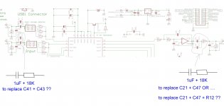
wima caps replacement ..
Hello,
I saw FreeDSP wima caps replacement information on ...
https://www.diyaudio.com/forums/dig...-4-digital-crossover-board-9.html#post4285896
Please help me to understand proper schematic ..
2 WIMA caps in parallel --> to one 1uF in series with 18K resistor or ??
Can someone draw which components ( 2 wima caps + resistors or only they .. ) can be replaced by one 1uF in series with 18K resistor ??
What means "per channel, or use 2 in parallel." ? ...
Best regards,
Emil
Attachments
NEW BOARD + CAPACITORS
Hello everyone!
I would like to buy my first DSP card, the FreeDSP Classic SMD B, but I am undecided because I also found this card similar but very complete and well done, in my opinion
AudioDSP - development board with DSP SigmaDSP ADAU1701 processor - Kamami
What do you think? Can you advise me?
Then in order to avoid the 47mF polarized capacitors in series on the inputs and outputs on this card can I put the 1mf WIMA? How can i do to replace the polarized capacitors?
Thanks in advance for your advice
Attachments
Member
Joined 2018
Hello, DIY lovers!
I just makin' same concept board. (I didn't know this project...)
Current my project URL is here
DIY DSP PROCESSOR PROJECT PAGE
(Currently in evaluation, not finished yet)
Features:
- 2in 4out ADAU1701 Single DSP Board
- DC12V Single Power Supply
- 2V RMS Input & 2V RMS Output
- Phase Inverted Output
- ON/OFF Muting Circuit
- Dual EEPROM
- I2S Expansion Headers (FreeDSP, Proprietary)
- Embedded Trim VR
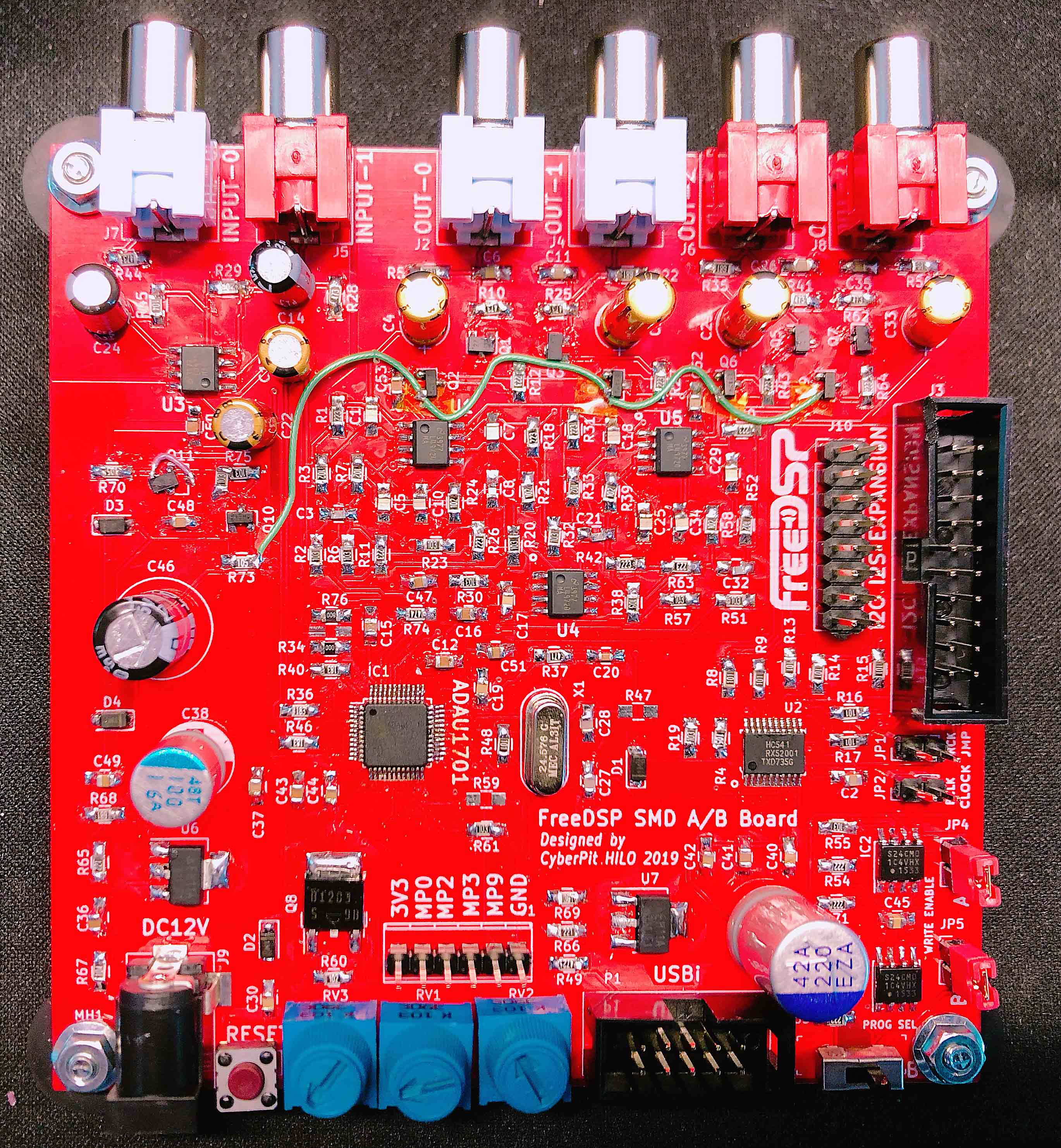
Regards,
HILO
I just makin' same concept board. (I didn't know this project...)
Current my project URL is here
DIY DSP PROCESSOR PROJECT PAGE
(Currently in evaluation, not finished yet)
Features:
- 2in 4out ADAU1701 Single DSP Board
- DC12V Single Power Supply
- 2V RMS Input & 2V RMS Output
- Phase Inverted Output
- ON/OFF Muting Circuit
- Dual EEPROM
- I2S Expansion Headers (FreeDSP, Proprietary)
- Embedded Trim VR
Regards,
HILO
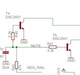
strange mute circuit.not sure if that works as intended. best to use a specialmute transistor, with the base weakly biased to a neg rail.to mute saturate the npn from a 3.3V rail using a pfet. generate a neg rail using a sw c charge pump using a clk like a LRCK or bclk from a serial DSP port, as it is only neg bias no curretn need to be delivered
Member
Joined 2018
Hi basreflex-San,
Well, this is my original mute circuit. I never seen like this before.
I know it looks unusual, but it works as I expected.
So I inted to use this one for priventing form digital noises.
HILO
Well, this is my original mute circuit. I never seen like this before.
I know it looks unusual, but it works as I expected.
So I inted to use this one for priventing form digital noises.
HILO
Member
Joined 2018
Hi basreflex-San,
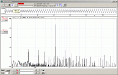
My original muting circuit almost works, but it was not perfect in the point of view of Audio design. Muting release action was not enough for audiophile use. Therefore I need to add negative power supply as you mentioned before. The actual test result was shown in following URL ...
DIY DSP PROCESSOR PROJECT PAGE
Thanks for your suggesting,
HILO
Attachments
Cyberpit-san
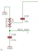
the neg rail can be simply done using a LRCK or BCK toggling at C35
the mute is done using a special mute transistor that can tolerate a high neg VBE, such that the CB diode does not add distortion. DSC2501, the collector is connected to the signal to be muted.
to mute pull the MUTE line high using a pfet out of 3.3V, when off the MUTE line is pulled to the neg rail by the 47k resistor. the neg rail can bias many mute transistors
Attachments
Last edited:
Member
Joined 2018
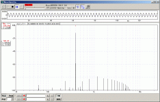
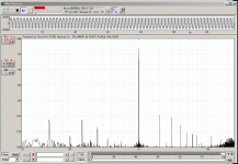
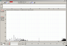
Negative Biased!
Hi basreflex-San,
Now I attached Charge-Pump card on my board. The result was very fine. I could know the ADAU1701 has a good enough embedded audio ADC/DAC performances (I changed my measuring USB-Audo I/F from 16bit to 24bit) 48kHz. Using LRCK is suitable for this purpose, BCLK was too fast to drive with single-ended FET. Next version board design will integrate this part.
HILO
Attachments
Last edited:
- Home
- Source & Line
- Digital Line Level
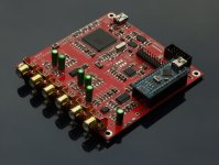
- freeDSP - an open source 2-in 4-out digital crossover board