If I was to use external D/A's, where do I connect I²S to them(on the FreeDSP board)? I assume you'd need two 2-channel D/A's?
Digital in:
Same question here really. If I want to connect a WM8804/WM8805 SPDIF to I²S board (in slave mode), where would I connect I²S output from said board?
If succesful in the above, I would need a way to control volume on the digital side. A "passive" digital preamp in other words.
Sorry about the, maybe, stupid questions... this is all relatively new to me.
If I was to use external D/A's, where do I connect I²S to them(on the FreeDSP board)? I assume you'd need two 2-channel D/A's?
Digital in:
Same question here really. If I want to connect a WM8804/WM8805 SPDIF to I²S board (in slave mode), where would I connect I²S output from said board?
If succesful in the above, I would need a way to control volume on the digital side. A "passive" digital preamp in other words.
Sorry about the, maybe, stupid questions... this is all relatively new to me.
Page 45 answers both of your questions: http://www.analog.com/media/en/technical-documentation/data-sheets/ADAU1701.pdf
In short the MultiPurpose Pins are exposed on JP2 on the FreeDSP classic board. You can configured these pins for whatever purpose you want: bclk, lrclk, sdata, and even analog control to connect to a POT for volume for whatever you want.
You would only need two 2 channel D/As if you want to support 4 independent channels out (technically you can do 4 I2S out - or 8 channels - plus the 4 builtin - but you wouldn't be able to do much DSP processing on all that data, especially at a higher sampling rate). Each I2S bus carries two channels of audio. The serial data is for the left or right channel based on the lrclk. The lrclk will cycle at the audio sampling frequency. E.g. if you're using 192khz, lrclk will be at 192khz.
Thank you very much
")
Seems I've got some reading to do.
Did a bit of reading and looking at the schematic etc.
By No means have I read the datasheet to a point of actually understanding it all lol.
Would the below be a step in the right the direction?
WM8805/8804 DATA to DSP JP2 pin 7
WM8805/8804 LRCLK to DSP JP2 pin 4
WM8805/8804 BCLK to DSP JP2 pin 5
And(this is less clear to me, using two DAC's)
DSP JP2 pin 9 to I²S DAC1
DSP JP2 pin 10 to I²S DAC1
DSP JP2 pin 11 to I²S DAC1
DSP JP2 pin 17 to I²S DAC2
DSP JP2 pin 10 to I²S DAC2
DSP JP2 pin 11 to I²S DAC2
GND to GND for all boards.
With reservation for me getting the pins wrong as I wrote them down.
I'm quite ready to give up on dsp based crossovers. I have tried, doublechecked and tripplechecked everything, even burnt one tweeter in the process. The two channels coming out of dsp are just - different, without any difference I could measure though, resulting in no imaging whatsoever. It's like shooting with camera out of focus. With push of a button, I switch to second speaker pair with passive XO, and everything drops in place - I can pick out each instrument on the stage right away. Starting to realize why is vast majority of speaker manufacturers still using passive xos.
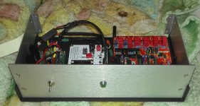
I've started putting the first FreeDSP board in to its enclosure.
I went with external PS (smps) for now as I don't know how much space will be left once all boards are in there.
The, ugly, perf board build is an AC or DC vreg set for +5Vdc. The white PCB is one of a few different versions of my WM8805 board, this one with datasheet input, apart from the PE65612.
I am not sure if I should use the PCB-mount RCA connectors or not. I'm leaning towards using "regular" panel mount connectors.
For the WM8805 SPDIF in, I'll use BNC.
I use one 1000uF before the vreg on the PS board, will that cause any issues with the smps?
IIRC, I've read that they are not always happy with large caps (I don't remember what the definition of large was in this case). I have two power supplies in mind, one 3A and one 5A, both 12Vdc.
The 3A one should be enough, if not I'll have to swap the vreg for an LT1083 based one (capable of 7A IIRC).
Attachments
Has anyone connected PCM2707 I2S with ADAU1701? As far as I can see, this is how it needs to be done:
PCM2707 adau1701
17(DOUT) ---> MP0 (SDATA_IN0)
5 (LRCLK) ---> MP4 (IN_LRCLK)
19(BCLK) ---> MP5 (IN_BCLK)
9 (FSEL) --> DGND (select I2S in PCM2707)
I found and reconfigured GPIO ports for respective functions. However, I am not sure how to switch between ADCs and I2S input, or is it done in SigmaStudio schematics?
I got the CY-something-something board today, the first of two ordered.
It was nearly impossible to get the drivers running under win 10 x64, or so I thought. I made changes with bcdedit etc... Finally I tried drivers downloaded earlier (in my FreeDSP-anything-related folder), and it worked like a charm.
So, anyone else having problems; use drivers from a download of the entire FreeUSBi git repository (clone or download as zip button).
That is after having disabled the *#*#*# win driver signature check.
It's getting close to me having to learn how to use Sigma studio lol.
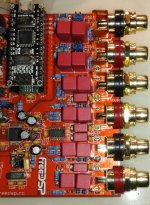
Got the second board done yesterday. The RCA jacks did have to be massaged gently with the Dremel to fit.
It was nearly impossible to get the drivers running under win 10 x64, or so I thought. I made changes with bcdedit etc... Finally I tried drivers downloaded earlier (in my FreeDSP-anything-related folder), and it worked like a charm.
So, anyone else having problems; use drivers from a download of the entire FreeUSBi git repository (clone or download as zip button).
That is after having disabled the *#*#*# win driver signature check.
It's getting close to me having to learn how to use Sigma studio lol.
Got the second board done yesterday. The RCA jacks did have to be massaged gently with the Dremel to fit.
Attachments
Has anyone connected PCM2707 I2S with ADAU1701? As far as I can see, this is how it needs to be done:
PCM2707 adau1701
17(DOUT) ---> MP0 (SDATA_IN0)
5 (LRCLK) ---> MP4 (IN_LRCLK)
19(BCLK) ---> MP5 (IN_BCLK)
9 (FSEL) --> DGND (select I2S in PCM2707)
I found and reconfigured GPIO ports for respective functions. However, I am not sure how to switch between ADCs and I2S input, or is it done in SigmaStudio schematics?
Does anyone know how to configure ADAU1701 schematics to accept I2S input and send to DACs?
I have no clue, I need to know the same thing soon.
I'm just waiting for some BNC concectors and jacks to show up so that I can hook up the WM8805 board. If I understood correctly, whatever board(s) you connect to the FreeDSP need to be in slave mode. I included that option in the WM8805 board more or less as a "why not?", lucky for me as I later started on the DSP project lol
I'm just waiting for some BNC concectors and jacks to show up so that I can hook up the WM8805 board. If I understood correctly, whatever board(s) you connect to the FreeDSP need to be in slave mode. I included that option in the WM8805 board more or less as a "why not?", lucky for me as I later started on the DSP project lol
Compiled, Comms Failed?
So,
I finally got the thumb out and hooked the FreeUSBi and FreeDSP up to my main PC(only one I have running win).
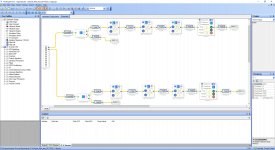
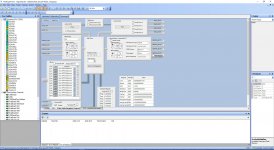
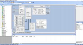
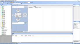
I did a first test schematic of a crossover that'll (hopefully) send an untouched signal to mid-highs of my dipole speakers and send a dipole compensated signal to the dipole woofers.
I intend to use external D/A's and WM8805 or maybe PCM2706 for I2S in, with the intentent to get better performance then with the onboard A/D and D/A, plus it would eliminate the A/D conversion completely.
But for this test-run I have it hooked up as I think it's supposed to be for using the onboard devices.
As I'm still waiting for some parts to finish building my WM-61A measuring mic/amp (directly as done on Mr. Linkwitz site), I was doing this as a test-run.
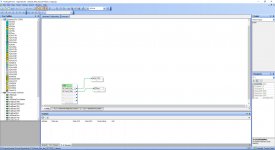
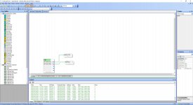
Now, all seem fine until I hit "Link Compile Download".
See attached pics.
I used eeprom I got off aliexpress as I didn't find the exact match, and know nothing on the subject, for the one called for in the BOM at any local source.
So,
I finally got the thumb out and hooked the FreeUSBi and FreeDSP up to my main PC(only one I have running win).
I did a first test schematic of a crossover that'll (hopefully) send an untouched signal to mid-highs of my dipole speakers and send a dipole compensated signal to the dipole woofers.
I intend to use external D/A's and WM8805 or maybe PCM2706 for I2S in, with the intentent to get better performance then with the onboard A/D and D/A, plus it would eliminate the A/D conversion completely.
But for this test-run I have it hooked up as I think it's supposed to be for using the onboard devices.
As I'm still waiting for some parts to finish building my WM-61A measuring mic/amp (directly as done on Mr. Linkwitz site), I was doing this as a test-run.
Now, all seem fine until I hit "Link Compile Download".
See attached pics.
I used eeprom I got off aliexpress as I didn't find the exact match, and know nothing on the subject, for the one called for in the BOM at any local source.
Attachments
Well, that seem to have been a embarrasing rookie move on my part. I had only soldered in the "corner pins" of the IDC connector. I was waiting on the cable connectors and wanted to make sure they fit before doing the rest of the pins. Somehow I forgot all about that lol.
About to try again with a fully connected board lol
About to try again with a fully connected board lol
Not much happening in this thread, maybe I'm late to the party so to speak?
Current status:
Both boards populated and working, atleast with the software (Sigma Studio).
I have two ES9023 I²S input boards (4 channels in total).
I have the following options for digital input:
PCM2706 (if it can be done with the board I have)
WM8805 board(s) that have SPDIF in and selectable output and master/slave.
WM8804 board (s) that will need to be modified to be able to run as slave.
I also have a DIR9001 on adapter, I suppose something could be perf boarded with that.
TDA1541A, I have 3 populated Red Baron V5 boards.
I don't know if they would work with the FreeDSP board?
If so, I may use one for the un-processed signal to mid/high, via amp of course, of my dipole speakers.
I do know they work OS with NPC SM5814 that I have a few of.
For power supply of the"external" boards I have some TPS7A4700 boards I had made recently.
I have yet to test them in any audio system, but from what I've read, they're supposedly good.
I think that is the extent of this project thus far.
USB isochronous i2s
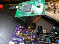
A neat way I have a freedsp board working is taking usb audio in via i2s. I'm using the fantastic amb zeta1 which is an implementation of audio widget. It works even driving the z1 from the onboard 12.288mhz xo. I'll probably remove the header from the DSP board and solder cables directly. This is just a poc for a DSP project I have that will include an audio widget atmel MCU and DSP on the same board.
A neat way I have a freedsp board working is taking usb audio in via i2s. I'm using the fantastic amb zeta1 which is an implementation of audio widget. It works even driving the z1 from the onboard 12.288mhz xo. I'll probably remove the header from the DSP board and solder cables directly. This is just a poc for a DSP project I have that will include an audio widget atmel MCU and DSP on the same board.
Attachments
- Home
- Source & Line
- Digital Line Level
- freeDSP - an open source 2-in 4-out digital crossover board