Hi
Planning on a little LM317 pre-regulator to supply clean power to an Audioquest Dragonfly. These were bought when they were selling for $100 each, now we want to get as much performance as possible.
Already noticed quite a big difference when using linear power supply on the whole PC (it's a tiny Atom with 7W max power consumption), but this DAC is for long-term use with a laptop which probably does not have very clean power to begin with, and then uses pretty basic stuff to knock down the voltage.
Now I know Gordon put seven power supplies in there so am not going for a fancy shunt regulator like I normally would, just an LM317 in series mode. Already confirmed that this has very good sonic results. However, am stuck at the signalling bit.
The first boards we built tended to lose sync on track change, so the driver was not correctly initialising. Also confirmed with a Benchmark DAC2, which knocked down to USB 1.0 mode and also has a sync problem on track change.
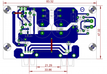
The PCB is totally unremarkable, and has about 1.2" of track between the two sockets. I was looking at pullup specs on the D+ and D- lines but could not tell whether I should pull them up on a high-speed device (full-speed and low-speed specs are clear). The only thing that strikes me is the differing trace widths for the ground and the signal lines, and the fact that there is no shielding for about 1.2" of track.
I am not sure it helps, but I attached a pic of the board here. The long output track will be cut for an inductor. Ignore the leftover routing traces, those aren't there on the final boards
Thanks for any insight you can provide.
Edit: The LED did have a series resistor in final production, I assure you
Planning on a little LM317 pre-regulator to supply clean power to an Audioquest Dragonfly. These were bought when they were selling for $100 each, now we want to get as much performance as possible.
Already noticed quite a big difference when using linear power supply on the whole PC (it's a tiny Atom with 7W max power consumption), but this DAC is for long-term use with a laptop which probably does not have very clean power to begin with, and then uses pretty basic stuff to knock down the voltage.
Now I know Gordon put seven power supplies in there so am not going for a fancy shunt regulator like I normally would, just an LM317 in series mode. Already confirmed that this has very good sonic results. However, am stuck at the signalling bit.
The first boards we built tended to lose sync on track change, so the driver was not correctly initialising. Also confirmed with a Benchmark DAC2, which knocked down to USB 1.0 mode and also has a sync problem on track change.
The PCB is totally unremarkable, and has about 1.2" of track between the two sockets. I was looking at pullup specs on the D+ and D- lines but could not tell whether I should pull them up on a high-speed device (full-speed and low-speed specs are clear). The only thing that strikes me is the differing trace widths for the ground and the signal lines, and the fact that there is no shielding for about 1.2" of track.
I am not sure it helps, but I attached a pic of the board here. The long output track will be cut for an inductor. Ignore the leftover routing traces, those aren't there on the final boards
Thanks for any insight you can provide.
Edit: The LED did have a series resistor in final production, I assure you
Attachments
Last edited:
D+ and D- are a differential pair and should be routed as such with as near to 90 Ohms diff impedance as possible. Though a minor impedance mismatch may not be to critical depending on what speed the USB is running at.
Do you know the noise spectrum of the laptop power output to for the USB?
That skinny join between the grounds it not very good...
Also you have no real RF/EMC filtering.....
Do you know the noise spectrum of the laptop power output to for the USB?
That skinny join between the grounds it not very good...
Also you have no real RF/EMC filtering.....
Hi Marce
Thanks for your reply.
The laptop power supply puts out ~150mV of noise. Not sure about the USB port, it's not been measured yet.
I would like the port to run at high speed. I will look at how to get the routing within spec.
I will also look at a more organised way to route the ground. Since I am not the board designer, I shall put forward the feedback and see how we go from there. Also thinking of a small resistor between the input and output ground, say an ohm or two, or an inductor.
Unfortunately this is a single ended board due to process constraints. Cannot incorporate ground plane, but I am going to have an output inductor after the regulator in the final product, in place of the jumper.
Should the D+ and D- lines also have a resistor in series between input and output? Or a pullup of some kind?
The USB pull up should be in either the DAC or the Laptop.
I would put the incoming USB ground through a ferrite bead to minimise any HF mush that may be on that line. The rest of the grounds you can then make as robust as possible.
USB is pretty robust and the constraints of the design make it hard for you to control the impedance.
I would put the incoming USB ground through a ferrite bead to minimise any HF mush that may be on that line. The rest of the grounds you can then make as robust as possible.
USB is pretty robust and the constraints of the design make it hard for you to control the impedance.
the noise culprit is the PC power supply, not the usb. it is ground injected noise coming from the swithed mode power supply. so even if the voltage between + and minus is clean, the noise coupledinto the gnd line wil be heards as soon as one of the receiving aparatus has some coupling to the mains lines through their supply.
one option is to use a clean DC/DC isolator and a usb isolator. you could build a LLC type fix freq dcdc, such that you can choose the freq relative to the dac freqs.
one option is to use a clean DC/DC isolator and a usb isolator. you could build a LLC type fix freq dcdc, such that you can choose the freq relative to the dac freqs.
Isolating limits the USB to a max of 12MHz if you use active devices such as the ADuM4160...
Then there are EMC considerations
http://www.analog.com/static/imported-files/application_notes/AN-0971.pdf
Then there are EMC considerations
http://www.analog.com/static/imported-files/application_notes/AN-0971.pdf
I managed to get the isolator to work with the Dragonfly, which is limited to USB 1.0 anyway (12mb/s). Playback in not much worse than a direct connection in terms of latency, but infinitely better in sound quality.
When the PC is powered by a linear supply the difference is much less but still there because the USB power is derived using switching regulators (PC uses a laptop-type plug for its power supply).
However there are still some data issues. With the combination connected the PC boots slowly but when it is disconnected or the DF connected directly to the port it boots in the usual five seconds. Obviously all is totally not well, but good enough for this particular peripheral. We will further try and match impedance of D+ and D- by making track lengths similar and try and keep it as close to symmetrical as possible.
- Status
- This old topic is closed. If you want to reopen this topic, contact a moderator using the "Report Post" button.
- Home
- Source & Line
- Digital Line Level
- USB power cleanup