Hi mates,
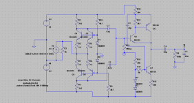
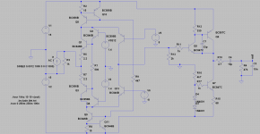
Thinking to an I/V for my PCM1704 based DAC, I though to this circuit in the afternoon. Basically it arise from the Pass Zen but with parallel BJT in order to keep low the input impedance for the DAC. Output stage is from a Self idea read in its "small signal audio design" book.
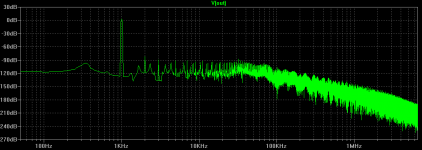
input of +/- 1.2mA from the PCM1704 gives 1.4Vrms output. It is a good compromise between distorsion, supply voltage and output. So here is the circuit and some simulations.
reconstruction filter could be placed after the decoupling caps before the base of Q5. I am thinking to a 6th order Bessel because DAC will be NOS.
Now I am all ears and eyes for your ideas about improving it
Thinking to an I/V for my PCM1704 based DAC, I though to this circuit in the afternoon. Basically it arise from the Pass Zen but with parallel BJT in order to keep low the input impedance for the DAC. Output stage is from a Self idea read in its "small signal audio design" book.
input of +/- 1.2mA from the PCM1704 gives 1.4Vrms output. It is a good compromise between distorsion, supply voltage and output. So here is the circuit and some simulations.
reconstruction filter could be placed after the decoupling caps before the base of Q5. I am thinking to a 6th order Bessel because DAC will be NOS.
Now I am all ears and eyes for your ideas about improving it
Attachments
Hi mates,
Thinking to an I/V for my PCM1704 based DAC, I though to this circuit in the afternoon. Basically it arise from the Pass Zen but with parallel BJT in order to keep low the input impedance for the DAC. Output stage is from a Self idea read in its "small signal audio design" book.
input of +/- 1.2mA from the PCM1704 gives 1.4Vrms output. It is a good compromise between distorsion, supply voltage and output. So here is the circuit and some simulations.
reconstruction filter could be placed after the decoupling caps before the base of Q5. I am thinking to a 6th order Bessel because DAC will be NOS.
Now I am all ears and eyes for your ideas about improving it
That will work.
The thing is - it has virtually zero power supply rejection. As such the power
supply is virtually directly in the signal path and is not a mysterious zero
impedance, perfect voltage source.
So then the situation becomes such that if you have designed a 'zero
feedback' current conveyor topology, for whatever reason, to follow through
with that approach, you should look at power supply also.
Or you can just use 337 / 317 and have some fun.
Z
Hi,
those simple current conveyor structures can sound extremly well.
That's the god point.
The topology shown here requires a first class power supply, due to the literally non-existant PSRR of the conveyor part.
There are several more points You may consider also:
- the supply voltages are way too high.
In a quick guess I say 9-15V will suffice, keeping heat power losses low enough without compromising on THD et al.
- Input impedance may be lowered with paralleling devices, increasing idle current or -most effective of all- going CFP style.
- the complementary conveyor 'hides' offset and temperature issues that may generate from the base voltage generators D1 and D6.
In a SE circuit the issues would be more obvious.
You may omit with the Diodes, using Q2 and Q4 in diode connection instead.
The BCs can be sourced as matched Duals in a commom casing.
Alternatively D1 and D6 may be replaced by complementars of Q1 resp. Q3 in grounded base connection.
They can also be sourced as complementary Duals in common casings.
- You could increase PSRR considerably and omit with the two 4.7uF coupling caps and one I/V resistor at the same if You replace the two 3k3 I/V resistors by current mirrors.
- the 1Meg base resistor of the CFP's Master transistor Q5 is way too high.
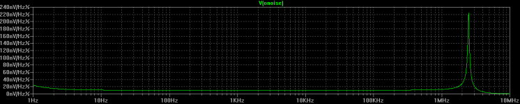
The base current of Q5 will generate considerable input offset voltage and noise.
- there are no bandwidth limiting measures taken within the I/V part nor at the input of the buffer part.
HF and too fast signals may enter the buffer.
- You may think about the choice of Q5.
The medium power transistor with lower hfe could be replaced by a small signal BC type
- the 3k3 collector resistor of Q5 is very high in value.
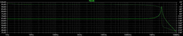
This limits the bandwidth and is probabely the source for the oscillation peak at ~1MHz too.
- a compensation cap or RC network from the CFP's Slave transistor Q6's collector to its base may kill the oscillation.
- a small valued emitter resistor for Q6 reduces parts tolerance sensitivity.
- a same small resistor could be inserted from the common node emitter Q5/collector Q6 to the output node.
- if the load following the buffer is high impedance and the additional current from the modulated current source Q7 is therefore not required, then omit with the modulation via R18/C5 alltogether.
The modulation is a possible source of oscillation.
A symmetrical current swing between buffer and current source could only be achieved into a specified lower ohmic load anyway.
Working into a high impedance load with very low current demand, the constant current source loaded buffer is the better choice - less parts, more stable and lower THD.
jauu
Calvin
ps
44.1k NOS requires high order reconstruction filters.
Besides the increased effort and tolerance sensitivity and drift, these filters are imho not sonically transparent.
It's my experience that linear upsampling to 176.4 kHz -or switched to 192kHz for 48kHz and 96kHz sources- together with simple low-order bandwidth limiting measurements within the I/V stage not only suffice technically, but sound more natural and transparent.
those simple current conveyor structures can sound extremly well.
That's the god point.
The topology shown here requires a first class power supply, due to the literally non-existant PSRR of the conveyor part.
There are several more points You may consider also:
- the supply voltages are way too high.
In a quick guess I say 9-15V will suffice, keeping heat power losses low enough without compromising on THD et al.
- Input impedance may be lowered with paralleling devices, increasing idle current or -most effective of all- going CFP style.
- the complementary conveyor 'hides' offset and temperature issues that may generate from the base voltage generators D1 and D6.
In a SE circuit the issues would be more obvious.
You may omit with the Diodes, using Q2 and Q4 in diode connection instead.
The BCs can be sourced as matched Duals in a commom casing.
Alternatively D1 and D6 may be replaced by complementars of Q1 resp. Q3 in grounded base connection.
They can also be sourced as complementary Duals in common casings.
- You could increase PSRR considerably and omit with the two 4.7uF coupling caps and one I/V resistor at the same if You replace the two 3k3 I/V resistors by current mirrors.
- the 1Meg base resistor of the CFP's Master transistor Q5 is way too high.
The base current of Q5 will generate considerable input offset voltage and noise.
- there are no bandwidth limiting measures taken within the I/V part nor at the input of the buffer part.
HF and too fast signals may enter the buffer.
- You may think about the choice of Q5.
The medium power transistor with lower hfe could be replaced by a small signal BC type
- the 3k3 collector resistor of Q5 is very high in value.
This limits the bandwidth and is probabely the source for the oscillation peak at ~1MHz too.
- a compensation cap or RC network from the CFP's Slave transistor Q6's collector to its base may kill the oscillation.
- a small valued emitter resistor for Q6 reduces parts tolerance sensitivity.
- a same small resistor could be inserted from the common node emitter Q5/collector Q6 to the output node.
- if the load following the buffer is high impedance and the additional current from the modulated current source Q7 is therefore not required, then omit with the modulation via R18/C5 alltogether.
The modulation is a possible source of oscillation.
A symmetrical current swing between buffer and current source could only be achieved into a specified lower ohmic load anyway.
Working into a high impedance load with very low current demand, the constant current source loaded buffer is the better choice - less parts, more stable and lower THD.
jauu
Calvin
ps
44.1k NOS requires high order reconstruction filters.
Besides the increased effort and tolerance sensitivity and drift, these filters are imho not sonically transparent.
It's my experience that linear upsampling to 176.4 kHz -or switched to 192kHz for 48kHz and 96kHz sources- together with simple low-order bandwidth limiting measurements within the I/V stage not only suffice technically, but sound more natural and transparent.
Last edited:
Hi mates!
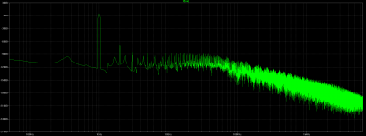
Yesterday brainstorming lead to this
Linearity is quite poor. About -70dB 2nd harmonic.
Output is now about 5Vpp
I think some shunt NFB is on its way.
R10, R11 and C1 dramatically improved output stage stability. It was very prone to oscillations before.
A question for Calvin:
Interesting thing about filtering. I understood that NOS at 44,1KHz leads to too much complicated filters in the analog domain.
Without using oversampling, I can simply convert the stream, using an ASRC, 44,1Khz to 96KHz (the maximum of PCM1704) and then cut at 22Khz with a simple filter because first aliased image appears at about 48Khz, right?
TODO:
- Apply some sort of shunt NFB
- Decoupling CCS
- Apply bandwidth limiting
- Insert the reconstruction filter before the base of Q5
Attachments
Last edited:
Hi,
What I also meant, was that ASRC is also not sonically transparent.
A 44.1kHz is sampled up to 96kHz by a uneven factor, which means that samples must continually be omitted with for re-synchronisation.
I think it´d be not only easier to upsample by even factors (44.1 to 88.2 or 176.4), but also sonically transparent and no loss of samples.
Once upsampled one may profit from less analogue post filtering.
I assume that it was simply a cheaper method that we nowadays find mostly ASRC, as SRC would require multiple clocks.
As a read download a DS of Realtek ALC982 and other Realtek Codecs.
Those can be found on Intel Mainboards.
Attached is a principle schem idea of a CFPed I/V converter Input stage with current mirroring.
CFPing allows very low and linear into the MHzes input impedances, a high factor of idle to signal current (low THD) and small base-biasing currents.
A sketch of how a dc-servo may be connected is included.
It requires less biasing- and reference voltages. In fact one simple Poti instead of R8 would suffice for trimming the circuit, two if no dc-servo is used
The Dual SMDs BC807/817 may be used as well as FZT651/751 for the CFP transistors.
Those transsistors may also be used for a diamond or improved diamond buffer.
jauu
Calvin
Yes, and that is exactly what I think too -and anm quite sure I wrote it that wayI understood that NOS at 44,1KHz leads to too much complicated filters in the analog domain.
What I also meant, was that ASRC is also not sonically transparent.
A 44.1kHz is sampled up to 96kHz by a uneven factor, which means that samples must continually be omitted with for re-synchronisation.
I think it´d be not only easier to upsample by even factors (44.1 to 88.2 or 176.4), but also sonically transparent and no loss of samples.
Once upsampled one may profit from less analogue post filtering.
I assume that it was simply a cheaper method that we nowadays find mostly ASRC, as SRC would require multiple clocks.
As a read download a DS of Realtek ALC982 and other Realtek Codecs.
Those can be found on Intel Mainboards.
Attached is a principle schem idea of a CFPed I/V converter Input stage with current mirroring.
CFPing allows very low and linear into the MHzes input impedances, a high factor of idle to signal current (low THD) and small base-biasing currents.
A sketch of how a dc-servo may be connected is included.
It requires less biasing- and reference voltages. In fact one simple Poti instead of R8 would suffice for trimming the circuit, two if no dc-servo is used
The Dual SMDs BC807/817 may be used as well as FZT651/751 for the CFP transistors.
Those transsistors may also be used for a diamond or improved diamond buffer.
jauu
Calvin
Attachments
Last edited:
A 44.1kHz is sampled up to 96kHz by a uneven factor, which means that samples must continually be omitted with for re-synchronisation.
I think it´d be not only easier to upsample by even factors (44.1 to 88.2 or 176.4), but also sonically transparent and no loss of samples.
In both cases you will have to employ an interpolation filter, so the samples will be altered, and the operation might or might not be sonically transparent.
Hi,
The interpolation simply adds new samples between the original samples.
As such it doesn´t need to alter the original samples or worse, omit alltogether with complete original samples.
As such even simple linear interpolation is a closer approach to the original analog signal.
But the most effective sonic mechanism is pobabely the lower analogue post filtering demand due to the increased clock rate
jauu
Calvin
I don´t agree.In both cases you will have to employ an interpolation filter, so the samples will be altered, and the operation might or might not be sonically transparent.
The interpolation simply adds new samples between the original samples.
As such it doesn´t need to alter the original samples or worse, omit alltogether with complete original samples.
As such even simple linear interpolation is a closer approach to the original analog signal.
But the most effective sonic mechanism is pobabely the lower analogue post filtering demand due to the increased clock rate
jauu
Calvin
What I also meant, was that ASRC is also not sonically transparent.
A 44.1kHz is sampled up to 96kHz by a uneven factor, which means that samples must continually be omitted with for re-synchronisation.
I think it´d be not only easier to upsample by even factors (44.1 to 88.2 or 176.4), but also sonically transparent and no loss of samples.
It is not about losing or gaining samples (that doesn't really matter)...
Oversampling is convolution : take your FIR filter, overlay it on the input samples, multiply and accumulate.
Oversampling to an integer multiple is simple because input and output samples "line up", so you can precalculate your FIR.
However when oversampling with a non-integer ratio, you can't precalculate the filter... for every sample you need to recalculate the filter values at the input sample times. If you do it in a PC you can just use double precision floating point and actually compute the sin(x)/x ; but in realtime on a silicon chip, it is going to involve sinus tables and interpolation.
Also in an ASRC, the input/output sample rate ratio is not fixed, it is measured in real time. When the clocks drift, it will change. But this number is measured on a fixed number of bits... then you can wonder how many bits it uses and wether slow clock drift will cause steps or not. (This is the reason it is recommended to use ASRC with an output rate that is not closely related to the input rate).
Since the silicon area and cost of the chip are going to be related to the precision of these calculations, you can bet that the amount of rounding errors has been "optimized" to just meet the THD spec and not cost 1 cent more.
ESS has found the way. They oversample to a very high frequency, with integer ratio and precalculated fiters, then the ASRC is a simple linear interpolation between samples, and there is no need to downsample them since they're sent directly to the modulator. ie, it is much easier to do an ASRC from 44.1k to 8 MHz, than 44.1k to 96k.
The interpolation simply adds new samples between the original samples.
As such it doesn´t need to alter the original samples or worse, omit alltogether with complete original samples.
That would only be true with a simple linear interpolation - but that would be a rather sub-optimal way to do things.
This is again one of those things where "intuitive analogies" lead you astray.
Hi,
thank You so much Peufeu for Your good explanation.
Julf, Yes that´d be suboptimal.
AfaIk Philips used the same sample four times to create the oversampled samples with their 14Bit-4x DACs, no interpolation at all.
What would be the optimal way in Your view?
There are more refined interpolation methods than the simple linear interpolation.
I just meant to point out that the simplest method aleady offers closer resemblance to the analog world than NOS.
jauu
Calvin
The Philips TDA1540 is a bit of a strage beast, as it used digital feedback, so there was interpolation, but in a somewhat complicated fashion.AfaIk Philips used the same sample four times to create the oversampled samples with their 14Bit-4x DACs, no interpolation at all.
The standard way is to insert samples with the value zero, and then use a sinc interpolation filter. In the case of a FIR filter, the zeroes make the calculation somewhat easier in the case of an integer multiple oversampling compared to a non-integer ratio, but in the case of an IIR filter, the complexity of the filter is the same in both cases. edit: I see that peufeu already explained that much betterWhat would be the optimal way in Your view?
I agree.I just meant to point out that the simplest method aleady offers closer resemblance to the analog world than NOS.
Last edited:
- Status
- This old topic is closed. If you want to reopen this topic, contact a moderator using the "Report Post" button.
- Home
- Source & Line
- Digital Line Level
- yet another I/V