5.6448M SC-3, 11 dBm output.
Impressive performance, really at the noise floor of the HP3048 HP 3048A What did you use as a reference oscillator? That system doesn't support cross correlation so the reference oscillator is critical.
That link is a great intro into phase noise measurement. The 3048's core is a box with mixers and a low noise preamp + other stuff to drive a PLL. The system also uses a PC and spectrum analyzers and synthesizers. Lots of stuff.
Andrea_mori (or anyone who knows):
First, nice work on this project!
Questions:
I'm looking over the PDF plans (found elsewhere in this thread) for the Driscol, Clapp, Pierce oscillators now
I see that the value of capacitors (e.g., C1, C2) vary based on crystal frequency.
Did you compute the suggested values using a formula (equation)? Or did you look them up in a table or spreadsheet?
Thx!
Andrea_mori (or anyone who knows):
First, nice work on this project!
Questions:
I'm looking over the PDF plans (found elsewhere in this thread) for the Driscol, Clapp, Pierce oscillators now
I see that the value of capacitors (e.g., C1, C2) vary based on crystal frequency.
Did you compute the suggested values using a formula (equation)? Or did you look them up in a table or spreadsheet?
Thx!
For the Clapp oscillator you can use these formulas:
C1 = C2 >= 1000 / f0 in pF for fundamental crystals
C1 = C2 >= 1000 / f3rd or f5th in pF for overtone crystals
L4 = 1 / (6.28 * (>f0)) ^2 * C2 in Henry for 3rd overtone crystals
L4 = 1 / (6.28 * (>f3rd)) ^2 * C2 in Henry for 5th overtone crystals
For the Driscoll oscillator use these formulas:
L4-C1 tuned just above the resonance of the crystal
L2 any value larger 2 to 20 times the reactance than what will resonate with the crystal's C0
R1 has to be choosen as a ratio to R, so as to provide enough gain for the circuit to oscillate. The crystal's ESR increases, the higher the value of R1
A starting point could be ESR * 20 in ohm. High ESR such as 40-50 ohm or more (SC-Cut cystals) needs active device (Q1) with higher hfe
L4 should be selected to have a high shunt impedance with respect to R1, and still resonate at or just below the oscillation frequency. A starting point could be an impedance value around 3 times the resistance of R1: (R1 * 3) / (6.28 * f0) in Henry. Then C1 is selected to resonate just above the resonance of the crystal
C2 should be as large as possible to provide a low impedance load and high Q for the crystal (the lower the impedance, the higher the loaded Q, the lower the phase noise), with R2C2 providing a large phase lag without too much gain loss. A starting point could be the following formula: 1 / f0 in MHz * 500 in pF
R2 is selected in the range 150-600 ohm depending on the ESR of the crystal. The higher the value, the higher the phase lag, the lower the impedance, the higher the loaded Q, but the higher the gain loss. If the gain loss is too high the oscillator does not start.
R3 controls the transistor’s DC current and is selected to get the the transistor’s DC collector voltage at half the power supply
You can simulate the results in LT Spice, usually the simulation is enough realistic.
Obviously, after the simulation each oscillator has to be tested in the real world, that's what I have done to define the values indicated in the tables.
Last edited:
A few more quick questions (I'm too lazy to research this thread or the topic!).
In all the clocks I use (or have built), they output a sine wave. Of course, I am ignorant about clocks other than a superficial know-how.
What are the 'Squarer' options for?
Is there any page/post(s) in this thread with o'scope display images of various TWTMC designs and configs?
Thx!
In all the clocks I use (or have built), they output a sine wave. Of course, I am ignorant about clocks other than a superficial know-how.
What are the 'Squarer' options for?
Is there any page/post(s) in this thread with o'scope display images of various TWTMC designs and configs?
Thx!
Was going over some osc. tutorials on YouTube.
The vlogger here recommends a snubber for the Vcc pin for the 74-series logic chip:
YouTube--Clock Sine wave/Square wave oscillator
The vlogger here recommends a snubber for the Vcc pin for the 74-series logic chip:
YouTube--Clock Sine wave/Square wave oscillator
For the Clapp oscillator you can use these formulas:
C1 = C2 >= 1000 / f0 in pF for fundamental crystals
C1 = C2 >= 1000 / f3rd or f5th in pF for overtone crystals
L4 = 1 / (6.28 * (>f0)) ^2 * C2 in Henry for 3rd overtone crystals
L4 = 1 / (6.28 * (>f3rd)) ^2 * C2 in Henry for 5th overtone crystals
For the Driscoll oscillator use these formulas:
L4-C1 tuned just above the resonance of the crystal
L2 any value larger 2 to 20 times the reactance than what will resonate with the crystal's C0
R1 has to be choosen as a ratio to R, so as to provide enough gain for the circuit to oscillate. The crystal's ESR increases, the higher the value of R1.
A starting point could be ESR * 20 in ohm. High ESR such as 40-50 ohm or more (SC-Cut cystals) needs active device (Q1) with higher hfe
L4 should be selected to have a high shunt impedance with respect to R1, and still resonate at or just below the oscillation frequency. A starting point could be an impedance value around 3 times the resistance of R1: (R1 * 3) / (6.28 * f0) in Henry. Then C1 is selected to resonate just above the resonance of the crystal
C2 should be as large as possible to provide a low impedance load and high Q for the crystal (the lower the impedance, the higher the loaded Q, the lower the phase noise), with R2C2 providing a large phase lag without too much gain loss. A starting point could be the following formula: 1 / f0 in MHz * 500 in pF
R2 is selected in the range 150-600 ohm depending on the ESR of the crystal. The higher the value, the higher the phase lag, the lower the impedance, the higher the loaded Q, but the higher the gain loss. If the gain loss is too high the oscillator does not start.
R3 controls the transistor’s DC current and is selected to get the the transistor’s DC collector voltage at half the power supply
You can simulate the results in LT Spice, usually the simulation is enough realistic.
Obviously, after the simulation each oscillator has to be tested in the real world, that's what I have done to define the values indicated in the tables.
Hello Andrea,
Could you please tell me also the formulas that you use for Pierce with fundamental crystal? I am interested more on the capacitor calculator and the R1
I want to build different variation of your Pierce design with cheap oscillators from Mouser(I can't find good ones there), and when I get the money I will buy the Laptech ones.
Using the info from here http://www.crystek.com/documents/appnotes/PierceGateLoadCap.pdf , the fact that the '04 inverter will have a 4p input and 6p output capacitance, and the info from you pierce table for the 22,5 /24,5Mhz crystals, I am getting that the C load should be ~33.5p. Is that the number that the Laptech crystals demands on the load? I don't really thinks so, it is to big, what I am missing?
Because I will not have access to hi-end equipment to test the oscillator, only an oscilloscope for verifying the wave form, I am thinking to use a FFT to measure my DAC output to have an idea if the clock modification is a good or bad one - could a FFT graph could be enough to reflect the different variation of the clock?
I did start from the crystal's manufacturer specifications, the suggested load capacitance is around 16.5 pF.
Then I did check the circuit in simulation, adjusting the component values (C1, C3 but also C2 and R1) to get right drive level (around 300uW), avoiding overvoltage at the input of U1A. The 22.5792 MHz AT crystal is specified for a max drive level of 400uW, so I choose a relatively high drive level (within the specifications) that tipically means lower phase noise. Remember that overvoltage at the input of the first gate affects the distortion and consequently the phase noise.
Finally, since I can't afford a 100000 USD phase noise measurement system, I did check the result in the real world using a standard 100 MHz oscilloscope. Component values were adjusted to get the best output waveform, again avoiding overvoltage at the input of the first gate.
Anyway, referring to the Crystek document, take a look at the equation of the sensitivity: the lower the motional capacitance, the lower the sensitivity. The Laptech crystal is specified for a motional capacitance around 14fF, so the sensitivity is very small.
Moreover in digital audio we don't care about long therm stability or absolute frequency, the most important parameter is the phase noise, that's affected mainly from the short therm stability.
Hi ... & a Happy New Year to you (& all) ")
If you look into this thread:
Building a phase noise measurement system for digital audio
... from post #7 there's a discussion of some issues & ideas for damping.
Personally I intend to try out a few different solutions - hoping that a small block of Panzerholz combined maybe with something like "EAR ISODAMP SD" will be sufficient in practice.
Cheers,
Jesper
Any ideas that will dampen vibrations?
If you look into this thread:
Building a phase noise measurement system for digital audio
... from post #7 there's a discussion of some issues & ideas for damping.
Personally I intend to try out a few different solutions - hoping that a small block of Panzerholz combined maybe with something like "EAR ISODAMP SD" will be sufficient in practice.
Cheers,
Jesper
Thanks Jesper, and a happy new year to you too.
I've played around with various materials underneath oscillators which did have effects on the sound, not sure if it was necessarily better of worse, just different. I'll look into your suggestions.
Thanks for the link.
Ryan
I've played around with various materials underneath oscillators which did have effects on the sound, not sure if it was necessarily better of worse, just different. I'll look into your suggestions.
Thanks for the link.
Ryan
Happy new year to all.
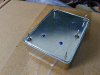
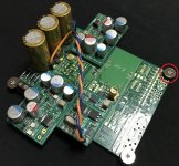
If you have implemented the TWTMC-D&D to supply the oscillator you can use rubber O-ring as in the attached picture (I used O-ring supplied by Ian).
Without the TWTMC-D&D, you can anyway solder the oscillator board to a simple stripboard (prototyping PCB) and then use the same tecnique.
If you have implemented the TWTMC-D&D to supply the oscillator you can use rubber O-ring as in the attached picture (I used O-ring supplied by Ian).
Without the TWTMC-D&D, you can anyway solder the oscillator board to a simple stripboard (prototyping PCB) and then use the same tecnique.
Attachments
Thanks Andrea, the photo explains a lot. I'm just about to order the parts for the TWTMC-D, so a while off mounting anyhow...
I'm going to try out those LT3042 regs that canvas is using. I might try feeding the 6V reg with a few lithium cells I have here and do a comparison with a mains fed supply.
Really looking forward to trying this one out. I'll let you know how I go.
I'm going to try out those LT3042 regs that canvas is using. I might try feeding the 6V reg with a few lithium cells I have here and do a comparison with a mains fed supply.
Really looking forward to trying this one out. I'll let you know how I go.
Another method:
Try vibration dampers with isolated washers.
Transfer Multisort Elektronik - On-line Catalogue | 200 000 products offered.
Try vibration dampers with isolated washers.
Transfer Multisort Elektronik - On-line Catalogue | 200 000 products offered.
Another method:
Try vibration dampers with isolated washers.
Transfer Multisort Elektronik - On-line Catalogue | 200 000 products offered.
Thanks for the link.
first impressions: twtmc-d, sc-cut
i want just briefly to share my finding regarding the mtwmt-d.
i am a satisfied user of bbb->hermes->cronus/rhea (45mhz and 49mhz) connected directly to a dddac.
following this very interesting thread - thanks a lot to andrea!!!! - i was very keen to test the cronus with twtmc-d / sc-cut quartz.
because some people reported that the sc-cut quartz does not necessary require an oven and there is no (or only minor) differences in sound performance using the oven, i have first decided to test the board without the oven.
i have currently replaced only the 45mhz Crystek CCHD-957 on the cronus.
the twtmc-d is supplied by two 3.3v and 6v regulators, both using 2x parallel lt3045. the complete audio source is supplied by 3x lifepo4 batteries. the twtmc-d is connected through a 5cm u.fl->u.fl cable to cronus. as the reference the remaining 49mhz Crystek quartz on the cronus is also supplied by a separate 3.3v lt3045 regulator.
the common tantalum input caps (47uf) on the lt3045 boards have been replaced by silmic2 which to my taste deliver a more detailed and "balanced" sound.
my twtmc-d has no trap and works fine with BRF 182 for the desired 45mhz.
results:
the improvement in the sound quality is immediately audible. however, it improves even more after a burn-in time of just one day.
the sound gets more dynamic in the details, more natural, more "air" and the sound stage becomes more "clear" and the music can surely be followed more relaxed. i would like describe my impression in the sound quality imrovement as if "micro gaps" in the music flow get closed!
i was/am very satisfied with the results , however, i was curious how the difference would be by using the oven. so during a listening session we heated up the sc-cut quartz using a hair dryer ( ) to approx. 80°-100°c . i was very positively surprised to hear the sound improvement as the crystal is getting hot! the sound became significantly more "organic", very relaxed , very emotional so i was quite impressed , especially i did not expect such a significant difference! once you have experienced this relaxed sound, you don't want to go back! so in my opinion the oven is a must for the sc-cut.
the next step is now clear; get the oven up and running! :-D
special thanks again to andrea , and also to all other diy members for keeping us busy enjoying the music
best wishes
i want just briefly to share my finding regarding the mtwmt-d.
i am a satisfied user of bbb->hermes->cronus/rhea (45mhz and 49mhz) connected directly to a dddac.
following this very interesting thread - thanks a lot to andrea!!!! - i was very keen to test the cronus with twtmc-d / sc-cut quartz.
because some people reported that the sc-cut quartz does not necessary require an oven and there is no (or only minor) differences in sound performance using the oven, i have first decided to test the board without the oven.
i have currently replaced only the 45mhz Crystek CCHD-957 on the cronus.
the twtmc-d is supplied by two 3.3v and 6v regulators, both using 2x parallel lt3045. the complete audio source is supplied by 3x lifepo4 batteries. the twtmc-d is connected through a 5cm u.fl->u.fl cable to cronus. as the reference the remaining 49mhz Crystek quartz on the cronus is also supplied by a separate 3.3v lt3045 regulator.
the common tantalum input caps (47uf) on the lt3045 boards have been replaced by silmic2 which to my taste deliver a more detailed and "balanced" sound.
my twtmc-d has no trap and works fine with BRF 182 for the desired 45mhz.
results:
the improvement in the sound quality is immediately audible. however, it improves even more after a burn-in time of just one day.
the sound gets more dynamic in the details, more natural, more "air" and the sound stage becomes more "clear" and the music can surely be followed more relaxed. i would like describe my impression in the sound quality imrovement as if "micro gaps" in the music flow get closed!
i was/am very satisfied with the results , however, i was curious how the difference would be by using the oven. so during a listening session we heated up the sc-cut quartz using a hair dryer (
) to approx. 80°-100°c . i was very positively surprised to hear the sound improvement as the crystal is getting hot! the sound became significantly more "organic", very relaxed , very emotional so i was quite impressed , especially i did not expect such a significant difference! once you have experienced this relaxed sound, you don't want to go back! so in my opinion the oven is a must for the sc-cut.the next step is now clear; get the oven up and running! :-D
special thanks again to andrea , and also to all other diy members for keeping us busy enjoying the music
best wishes
Pretty much like what I experienced. The oven makes difference! This XO needs a long time to burn-in. I found minor improvements even after 1000 hrs of power up. Be sure to use separate winding for clock board and oven. BTW, I prefer PO74G04 more than VHC logic.
thanks for the remarks, i will try the PO-type. for the oven i am going to use a separate 16v-psu (incl. its own transformer) as well. the rest of the audio source is supplied by batteries.
best regards
- Status
- Not open for further replies.
- Home
- Source & Line
- Digital Line Level
- The Well Tempered Master Clock - Building a low phase noise/jitter crystal oscillator