One more question: The ADC I intend to use this clock with is rather old (but of the SAR variant) and speced at 50 ps RMS aperture jitter. Is this only relevant for the noise level (which is below my analog noise floor and I thus consider it irrelevant) or does it make an ultra low phase noise clock useless?
What I care for is a natural timbre and clear spatial/dynamic sound.
What I care for is a natural timbre and clear spatial/dynamic sound.
I don't understand why all of these elements are supposed to go in seperate boxes, connected by BNC cables.
Why don't you use a single case for clock, converter, sine2square etc.?
Well, the cables are SMA terminated and not BNC.
You are free to use a single case for all the devices but it's not a good practice.
These are RF devices that generate a lot EMI/RFI and they can interfere among them, mostly if you put oscillators at different frequency in the same box.
So I suggest separate boxes for the oscillators, then you can put the sine to square converters close to the DAC (or the FIFO).
One more question: The ADC I intend to use this clock with is rather old (but of the SAR variant) and speced at 50 ps RMS aperture jitter. Is this only relevant for the noise level (which is below my analog noise floor and I thus consider it irrelevant) or does it make an ultra low phase noise clock useless?
What I care for is a natural timbre and clear spatial/dynamic sound.
As I said several times the jitter is almost useless to understand the quality of a clock because it's a standalone number that not explain nothing about the spectrum of the noise.
What I can say is that several member in this thread have reported great improvement in sound when moving to a better oscillator, even using old DAC such as the TDA1541A.
The reason is that we are very sensitive to timing errors while we are not so sensitive to THD.
That's the reason why tube amplifiers with 2% THD sound much better than solid state amplifiers with 0.0000...% THD.
And the reason is almost the same since usually amplifiers with such low distortion use heavily negative feedback. The NFB introduce phase shift and we perceive it as a timing error.
Typically the result is a non natural sound, loss of details and mostly ambience error.
This is what I can say from my personal empirical experience, but obviously I cannot predict the result with your DAC.
TWTMC-STS_FSDO phase noise
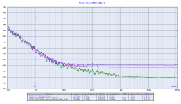
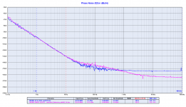
I attach the phase noise plots of the TWTMC-STS-FSDO (sine to square converter, fanaout/switched output) that implements the LTC6957.
The oscillator used to feed the TWTMC-STS-FSDO is the New Driscoll TWTMC-DRIXO at 5.6448 and 22.5792 MHz.
The plots show the phase noise comparison of the squarer against the sine wave oscillators.
The 5.6448 MHz plot includes also the measured phase noise of the TWTMC-STS-SX sine to square converter with the same oscillator.
There is not much difference, the LTC6957 is a little better close to the carrier (1 to 10 Hz) while the 74AC04 has a little better noise floor.
Attachments
Usually the sine to square converter is used with Ian's Fifo that provides a clean 3V3 supply.
I don't provide 3V3 linear regulator because we suggest the LiFePo4 battery supply for all the digital chain (it provides 3V3 power rail).
You can use whatever low noise 3V3 regulator (around 40 mA for 2 squarers).
If your device accept 5V clock you can also use a 5V low noise regulator, the 74AC04 performs better at 5V rather than at 3V3 power supply.
We suggest RG400 50 ohm cable 1 meter long (or so).
I have not yet provided the BOM for the TWTMC-PXO-AIO at 6.25 MHz because I was waiting to understand if the MOQ for the crystal was met, but since it looks like there are orders for 10 pcs I will publish the BOM soon, and also I will send the proforma invoice to the users who have opted for this solution.
I have not yet provided the BOM for the TWTMC-PXO-AIO at 6.25 MHz because I was waiting to understand if the MOQ for the crystal was met, but since it looks like there are orders for 10 pcs I will publish the BOM soon, and also I will send the proforma invoice to the users who have opted for this solution.
Andrea, what max. lenght can a SMA terminated cable be, between the oscillator box and the TWTMC-STS-FSDO board/box and between the TWTMC-STS-FSDO and a DAC etc.?
Is there a BOM for the 6.2500 MHz AT-cut, PXO-AIO-SF board?
I attach the Mouser BOM for the TWTMC-PXO-AIO with AT-Cut crystal at 6.25 MHz.
Attachments
And the reason is almost the same since usually amplifiers with such low distortion use heavily negative feedback. The NFB introduce phase shift and we perceive it as a timing error.
Typically the result is a non natural sound, loss of details and mostly ambience error.
Bob Cordell addressed the phase shift argument effectively years ago. While there may be phase shift modulation its not due to feedback. You can take up the issue here: Bob Cordell's Power amplifier book
And then there is a fundamental dichotomy in audio between accuracy and what sounds good. it always gets really difficult to figure out just what is the real cause of the perceived sonic effect. There are too many hidden variables.
Please, look at the first post of the GB thread
The Well Tempered Master Clock - Group buy
There you can find the links to the order form, to the guide of all the devices and to the shared spreadsheet where you can find MOQ and ordered quantity for each device.
Thanks Andrea. I still can not find pictures the complete PCB of TWTMC-DRIXO 24/25MHZ and the detail guide to diy, setup to my switch my Sotm Sms 200. Thanks again
- Status
- Not open for further replies.
- Home
- Source & Line
- Digital Line Level
- The Well Tempered Master Clock - Building a low phase noise/jitter crystal oscillator