Hi, I'm looking to nail the low pass filtering of a TDA1543 to a lower frequency (say 18-22kHz) with the use of an RLC low pass circuit, I was wondering if anyone would be able to help me with some values for the coil resistor and capacitor. (I'm no expert.)
http://sim.okawa-denshi.jp/en/RLCtool.php
The values that I get are:
680kOhm for resistor
0.00238 H for the coil
with 0.022uF for the capacitor.
How would I go at winding the coil?
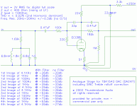
This would be a part of a passive I/V conversion process for the output.
Coupling capacitors are a K73-15B with a value of 0.022uF
Resistors would need to be of a sufficient value to provide 1-2v RMS output.
What would be the effect on the waveform of adding impedance (ie from a choke) to the output of a simple 16 bit non oversampling DAC with passive IV conversion? ex: TDA1541/1543
Would also be interested/curious as to what would happen to the waveform.
Thank you for your time.
Last edited:
From a quick sim on LTSpice, I get the following component values
R = 500R - this is the I/V resistor
L = 18mH
C = 3.3nF
You'll also need a resistor on the output, across the cap to provide dampling. This is 3k.
This is a very rough and ready first pass as aspects like the inductor's AC losses haven't been factored in. I've also assumed that it will feed into a high impedance load (no less than 47k). The load impedance has an impact on the damping and hence ringing.
You don't need to wind your own coil, Mouser has suitable 18mH chokes - http://www.mouser.com/ds/2/54/FSR1013-72226.pdf
From a quick sim on LTSpice, I get the following component values
R = 500R - this is the I/V resistor
L = 18mH
C = 3.3nF
You'll also need a resistor on the output, across the cap to provide dampling. This is 3k.
This is a very rough and ready first pass as aspects like the inductor's AC losses haven't been factored in. I've also assumed that it will feed into a high impedance load (no less than 47k). The load impedance has an impact on the damping and hence ringing.
You don't need to wind your own coil, Mouser has suitable 18mH chokes - http://www.mouser.com/ds/2/54/FSR1013-72226.pdf
Thank you very VERY much for that.
I like to pretend that I live here so I usually don't buy stuff from reputable component outlets:
Attachments
Classics, I L O V E old school!
You should start at NOS and work your way up!:
Old T:

and New CarlosFM

DIYHiFi.org • View topic - Understanding DSD

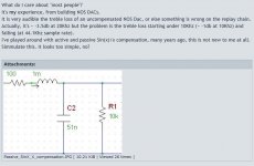
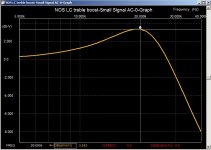
These are low z and high z for 1543 and NOS sinc rolloff correction.
PS CarlosFM also made a TINA opamp that was 2nd order and peaked at 20k for NOS sinc correction and then dropped like a stone .... (I'll let someone with better googleFU find it)
You should start at NOS and work your way up!:
Old T:

and New CarlosFM

DIYHiFi.org • View topic - Understanding DSD

These are low z and high z for 1543 and NOS sinc rolloff correction.
PS CarlosFM also made a TINA opamp that was 2nd order and peaked at 20k for NOS sinc correction and then dropped like a stone .... (I'll let someone with better googleFU find it)
Last edited:
From my memory of the NOS droop that graph looks overly 'hot' (i.e. applies too much lift). I've played with an LC LP filter which rings up and found a closer match to the required curve comes from setting the resonance a tad higher in frequency. But then I'm only interested in correcting up to 18kHz as my hearing's shot beyond that for sure....
- Status
- This old topic is closed. If you want to reopen this topic, contact a moderator using the "Report Post" button.
