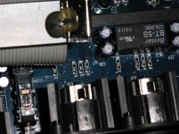
Be careful with the power supply. This is a switched power supply.
I will suggest you at start to mod only the two 470UF and the two 10UF before and after the 15V regulators.
- Replace C4 and C5 by 1000UF 35V with low ESR / hight ripple current (as Rubicon ZL). Will fit but you will have to push a little D1 and D2.
- Replace C1 and C2 by 47UF 25V tantalum (use good quality model as AVX Tap).
Write for reference, all voltage before and after regulators before tweaking. Write voltage with the digital card connected and without the digital card connected.
But the most important is to replace opamps.
I just found out that is only two 0.1uf decoupling caps for the four opamps. All the ceramics next to the opamps are for filter circuit, the 2 decoupling caps are located much further away.
The opamp will be replaced by lm6172, but I will definitely replace the whole output stage later when I have more time.
The opamp will be replaced by lm6172, but I will definitely replace the whole output stage later when I have more time.
I have the DEQ with a complete 'new caps' power supply for a week and all is fine. 
For the caps on the analog board, I waiting for an Black Gate PK source.
We have a thread there but in French. You can have a look on the pictures.
http://www.homecinema-fr.com/forum/viewtopic.php?t=29744761&highlight=
For the caps on the analog board, I waiting for an Black Gate PK source.
We have a thread there but in French. You can have a look on the pictures.
http://www.homecinema-fr.com/forum/viewtopic.php?t=29744761&highlight=
Hi Stef1777,
may I recommend not the use the PK grade blackgate, I have use those before and find them not very effective and not worth the price. I would probably just use a higher value ZL which also fits. Just my opinion.
Also, I have tested some the ecaps on the output board and none of those are from the +/-15v rail. So I believe they are just for the relay.
Do you know why it has 4 dual opamp for the output, the ak4393 datasheet shows that output stage uses only 2 for balance out.
Could it be possible that using lower gain will bypass 2 opamp?
ChuckT said:may I recommend not the use the PK grade blackgate, I have use those before and find them not very effective and not worth the price. I would probably just use a higher value ZL which also fits. Just my opinion.
Actualy as I don't realy know the use of the 7 ecaps close to the in/out, I haven't moved to replace them. The PK was not really expensive. Rubycon ZA seems better than ZL. 6.3mm caps can fit on the analog board. Elna (all type) do not fit execpt if we change value or voltage.
Also, I have tested some the ecaps on the output board and none of those are from the +/-15v rail. So I believe they are just for the relay.
Do you know why it has 4 dual opamp for the output, the ak4393 datasheet shows that output stage uses only 2 for balance out.
Could it be possible that using lower gain will bypass 2 opamp?
I don't know sure but you have 2 stages. I changed the 7 opamps... but at start I was looking to put AOP2134 on input and AOP2604 on output. As not sure where are the right one, I changed all of them will the same opamp.
But be careful, Behringer's engineers are vicious.
The PCB is really FRAGILE.
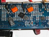
Coupling cap found
Ok, more probing shows that the ecaps next to the relay are coupling caps for the 1st opamp stage. There are 4, but I only trace the 2 to the opamp, the other two not sure.
So changing this should make a difference.
I put in Blackgate-N for the opamp coupling and cerafine for the other 2.
Ok, more probing shows that the ecaps next to the relay are coupling caps for the 1st opamp stage. There are 4, but I only trace the 2 to the opamp, the other two not sure.
So changing this should make a difference.
I put in Blackgate-N for the opamp coupling and cerafine for the other 2.
Attachments
Re: Coupling cap found
Sorry, but can you specify wich one are the coupling caps on the picture? What's the value of the new ecaps?
I'v hires pictures of the board without the 7 opamps if this can help to analyse the circuit.
Thanks.
ChuckT said:Ok, more probing shows that the ecaps next to the relay are coupling caps for the 1st opamp stage. There are 4, but I only trace the 2 to the opamp, the other two not sure.
So changing this should make a difference.
I put in Blackgate-N for the opamp coupling and cerafine for the other 2.
Sorry, but can you specify wich one are the coupling caps on the picture? What's the value of the new ecaps?
I'v hires pictures of the board without the 7 opamps if this can help to analyse the circuit.
Thanks.
ChuckT said:I believe the cap no is show in the pic, they are the 4 cap next to the relay. I believe they are 47uf, I use 33uf.
BTW, have you try the auto eq, does it stop by itself? It seems to go on forever and I just stop it. I couldn't get a very flat reponse!
I'ts never flat or if you try, you will break the music.
Read a little more the Manual. It's wrote inside.
Just push the button after 2mm, and click on DONE (next screen). Put delta max at 3 dB. The best is to switch to double mono mode. You can also use a destination curve as audio X-Curve. Great!
This not the right thread. You can open one "Use of DEQ23496" thread if you need.
Right. Thanks for the reply.
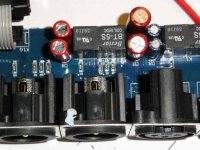
Back to the mod, I have added BG FK 100uf to the +/-15v supplies beneath the digital broad connector. I believe I have done as much as I can/want with the output stage. The next upgrade should be a new outstage!!
Well, maybe one more when I have time. There are various filtering smd caps in the opamp circuit that IMO are quite critical to the sound. The small values (100pf and 390pf, please correct me if I wrong) are likely to be NPO grade (unfortunately can not confirm) and no need to be change, however, the 2.2nf are critical and unlikely to be NPO (due to cost). So changing them to NPO smd should make an improvement. I have also found some pps film smd caps from Panasonic in Farnell that might fit.
Also, it may be possible to replace the 2 smd 0.1uf decoupling for the 4 output opamp to Blackgate NX-Q 0.47uf/50v.
Sorry, I've have no time to look at the DEQ right now. I'm leaving for my summer vacations by the end of the week.
I would again suggest you to publish pictures with red circles around of the different identified caps and your remplacement suggestion wrote on it. This is the best to understand and follow.
Concerning smd caps, Wima propose a Samples program. Have a look.
http://www.wima.com/navig/smdsp.htm
I would again suggest you to publish pictures with red circles around of the different identified caps and your remplacement suggestion wrote on it. This is the best to understand and follow.
Concerning smd caps, Wima propose a Samples program. Have a look.
http://www.wima.com/navig/smdsp.htm
It seems nothing has happened about this thread for a while...but I'll try anyway.
I've opened my deq2496 and (think I have) identified how the DAC op runs in the flat-cable to the op-board.
AK4393 has balanced op on pin 23,22(L) and 21,20(R). The op is 2,4Vpp so I believe it's suitable to be connected to a Zapfilter2 analogue op-stage:
http://www.lcaudio.dk/index.php?page=6
Attached picture shows DAC and flat-cable. I got the following results (DAC - cable):
23-7
22-8
21-10
20-11
Does anyone have a schematics where this can be confirmed? I would be very grateful for a schematics!
Maybe someone has done this already (completely new op-stage) and can share some useful or not so useful information
I've opened my deq2496 and (think I have) identified how the DAC op runs in the flat-cable to the op-board.
AK4393 has balanced op on pin 23,22(L) and 21,20(R). The op is 2,4Vpp so I believe it's suitable to be connected to a Zapfilter2 analogue op-stage:
http://www.lcaudio.dk/index.php?page=6
Attached picture shows DAC and flat-cable. I got the following results (DAC - cable):
23-7
22-8
21-10
20-11
An externally hosted image should be here but it was not working when we last tested it.
Does anyone have a schematics where this can be confirmed? I would be very grateful for a schematics!
Maybe someone has done this already (completely new op-stage) and can share some useful or not so useful information
Konnichiwa,
Sorry, I did not get around to doing any work on my DEQ...
In the meantime I have confirmed that the analogue stages gegernally match in terms of layout the ones in the DCX Crossover (screenscrapes from acrobat attached).
Input Circuit to ADC (this with the takeoff of the digital feed):
Output Circuit after DAC:
The +12dbu/+10dbv/3VRMS=0dbfs switch option links in there somewhere, not sure yet where. Ignore all the component numbers, they have no bearing on the DEQ, only the principle design is the same.
For those wanting SE Outputs at lower levels it is easy to just cut out a whole stage, remove the XLR Sockets and fit RCA ones.
Also, the various DC blocking capacitors should be possible to be simply eliminated and replaced by a wire, only one is really required, namely between the Input Stage first stage and the phasesplitter driving the ADC (marked C6 on that particular schematic). You may have to add some offset nulling in the analog stage after the DAC, but that is not a big deal.
Yes, if you can find the space to fit all neccesary bits that can be used. Depending upon your needs you could use much simpler circuitry.
Me too please, it makes work ever so much easier. I have been able to find the DCX2496 Schematics, but not the DEQ one. As said however, the basic structure between the analog stages of the DEQ and DCX matches, so the DCX schematic helps a little.
Sayonara
deerhunt said:It seems nothing has happened about this thread for a while...but I'll try anyway.
Sorry, I did not get around to doing any work on my DEQ...
In the meantime I have confirmed that the analogue stages gegernally match in terms of layout the ones in the DCX Crossover (screenscrapes from acrobat attached).
Input Circuit to ADC (this with the takeoff of the digital feed):
An externally hosted image should be here but it was not working when we last tested it.
Output Circuit after DAC:
An externally hosted image should be here but it was not working when we last tested it.
The +12dbu/+10dbv/3VRMS=0dbfs switch option links in there somewhere, not sure yet where. Ignore all the component numbers, they have no bearing on the DEQ, only the principle design is the same.
For those wanting SE Outputs at lower levels it is easy to just cut out a whole stage, remove the XLR Sockets and fit RCA ones.
Also, the various DC blocking capacitors should be possible to be simply eliminated and replaced by a wire, only one is really required, namely between the Input Stage first stage and the phasesplitter driving the ADC (marked C6 on that particular schematic). You may have to add some offset nulling in the analog stage after the DAC, but that is not a big deal.
deerhunt said:AK4393 has balanced op on pin 23,22(L) and 21,20(R). The op is 2,4Vpp so I believe it's suitable to be connected to a Zapfilter2 analogue op-stage
Yes, if you can find the space to fit all neccesary bits that can be used. Depending upon your needs you could use much simpler circuitry.
deerhunt said:Does anyone have a schematics where this can be confirmed? I would be very grateful for a schematics!
Me too please, it makes work ever so much easier. I have been able to find the DCX2496 Schematics, but not the DEQ one. As said however, the basic structure between the analog stages of the DEQ and DCX matches, so the DCX schematic helps a little.
Sayonara
Konnichiwa,
Armed with the Schematics from the DCX and some datasheets here are some thoughts of what I feel would likely make for the best I/O stages for the DEQ (and by extension the DCX). From a "purists" viewpoint I rather take a single high quality transformer instead of 3 - 4 Op-Amp's, tons of capacitors and so on. So, can we roll transformers in there easily?
First, if we consider the output from the DAC, 4.8V Peak-Peak (differential) with a 2.5V DC offset. The Output clearly can drive 1K2 differential, as example circuits show a pair of 620R Resistor to ground.
If we have the DEQ in +12dbu level setting we get nomainally 3V Output Voltage, which is 8.5V.
So, if we where to take a commercially available "universal" line transformer of the 2K5:10K Type offering a level handeling of at least +13dbu @ 50Hz and connect the 2K5 side across the output of the DAC we will have an output of actually 3.4V for full scale and we will be able to drive a load of 5K or higher. No need for anything more. The transformer will form a 2nd order lowpass.
A suitable type would be the Stevens & Billington TX896 (ideally with some minor mods). The transformer is rated with an 0.5db bandwidth of better than 45KHz, good enough for 96KHz converters, with +12dbu @ 40Hz level handling we have just the right level without having to use handgrenade sized transformers. DCR is around 200R per winding, so in stepup mode on the analogue output the output impedance will be around 1k2 resistive, not outstanding, but non too bad either.
If purchased theorugh the normal distribution channels they will probably run at around 75 - 85 US $ each (sorry the poor US $ Exchange rate really louses things up for non europeans) not cheap but if you count a bunch of non-polar Black Gates, SMD Op-Amp Adapters for OP627 etc. etc the costs ratchet up quickly too....
These will be a little hard to mount in the rather low hight of the case. The flying lead version simply bolted to the bottom of the case is taller than the case allows, placing them on their sides is difficult. Using the PCB version on a dedicated PCB might work well. Otherwise using a piece of suitable angled Aluminum should make the mounting easy enough, using the flying lead version. In either case there is enough space between the powersupply and the main DSP PCB to place them there, in the DCX it would be a little tighter a squeeze.
If we also need and option for +22db the transformer should also allow a 1:6 Stepup, but that is likely to cause interesting happenings, for once, the permissable load on the output would be very low. Hence the option would be not very usefull for studio users, but just fine for domestic use.
Now on to the analogue inputs. What can we do here? We need 4.9V Peak-Peak (differential) with a 2.5V DC offset to drive the ADC to clipping, but in the case of the Behringer gear a 10db Pad is in front of the ADC. If we remove the shunt resistor of the Pad we have a load onto whatever drives the ADC of nominal 4.6KOhm in parallel with a 600R/1.5nF Zobel.
If we where to use the same transformer as on the Output, but reverse (setdown mode) our source would see a load of around 18K in parallel with 375pF. Our transformer again will operate as lowpass, basically anything should be pretty peachy.
I suspect we could actually remove the RC lowpass on the DAC or at least scale it to lower C-Values if we want to do more SMD messing about than strictly needed. In that case, the Transformers own DCR will amount to around 300R effective feeding the inpouts of the ADC.
Thus removing all the resistors of the L-Pad and the Capacitor in parallel to the input and soldering the wires directly to the pins of the IC should work. Then add a sensible value (say 470pF polystyrene or Silver Mica) across the input and we should have an effective input impedance of around 17K nominal, in parallel with 120pF, a load that will work fine with virtually any active output stage from source gear and even most passive preamps. Full Scale input voltage would be 3.4V RMS.
There you go, universally balanced or unbalanced inputs and outputs for the DEQ2496 all fully passive, with levels appropriate to HiFi Gear (not Studio). The outputs have the same levels balanced & unbalanced and don't really give sack jit if you use them balanced or single ended....
Sayonara
Thanks for your detailed answers Kuei Yang Wang (T.L.).
I did have the Zapfilter laying around so this evening I've spent putting it into the DEQ2496.
Smoke is still inside the components (all electronics components contains smoke to function - if the smoke gets out the unit brakes down - 1st class of electronic engineering)
I can post a few pictures after the holiday.
Sounds good so far, I can make a small conclusion later.
Good Night
- Home
- Source & Line
- Digital Line Level
- Modify behringer DEQ2496?